
Hybrid wellhead system and method of use

a hybrid wellhead and wellhead technology, applied in the direction of sealing/packing, drilling pipes, borehole/well accessories, etc., can solve the problems of high construction and maintenance costs, high construction costs, and high construction costs, and achieve easy and more economical manufacturing and assembly, and low cost. , the effect of less cos

Active Publication Date: 2007-01-09
WELLS FARGO BANK NAT ASSOC +1
View PDF13 Cites 72 Cited by
  • Summary
  • Abstract
  • Description
  • Claims
  • Application Information

AI Technical Summary

Benefits of technology

The invention is a hybrid wellhead system that combines the high-pressure rating of a flanged wellhead with the ease-of-use and low cost of an independent screwed wellhead. It is designed to withstand high fluid pressures and minimize rig downtime. The system includes multiple tubular heads connected to a hybrid wellhead system by threaded unions and a tubing head spool mounted to the wellhead system with a flanged connection. The invention also provides a method for installing a wellhead for stimulating a well for the extraction of hydrocarbons.

Problems solved by technology

The downside of flanged wellheads (also known in the art as ranged wellheads) is that they are heavy, time-consuming to assemble, and expensive to construct and maintain.
Oil and gas companies are thus faced with a tradeoff between pressure rating and cost.
One of the disadvantages of the Smith casing nipple and method of use is that the casing nipple must be installed prior to fracturing and then removed prior to inserting the tubing string.
As persons skilled in the art will readily appreciate, the steps of installing and removing the casing nipple generally entail killing the well, resulting in uneconomical downtime for the rig and potentially reversing beneficial effects of the fracturing operation.

Method used


Image

  • Hybrid wellhead system and method of use
  • Hybrid wellhead system and method of use
  • Hybrid wellhead system and method of use

Examples


Embodiment Construction

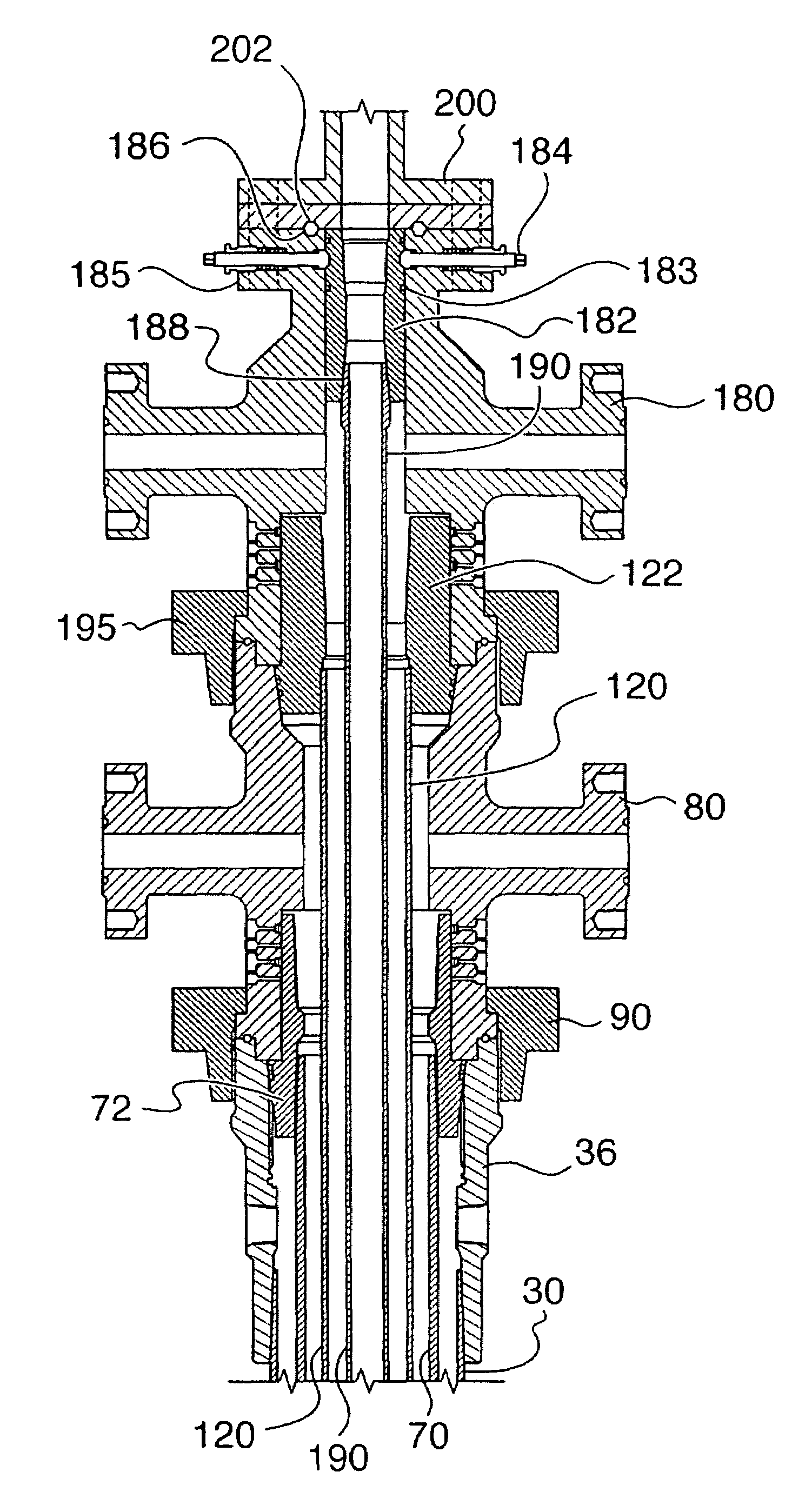
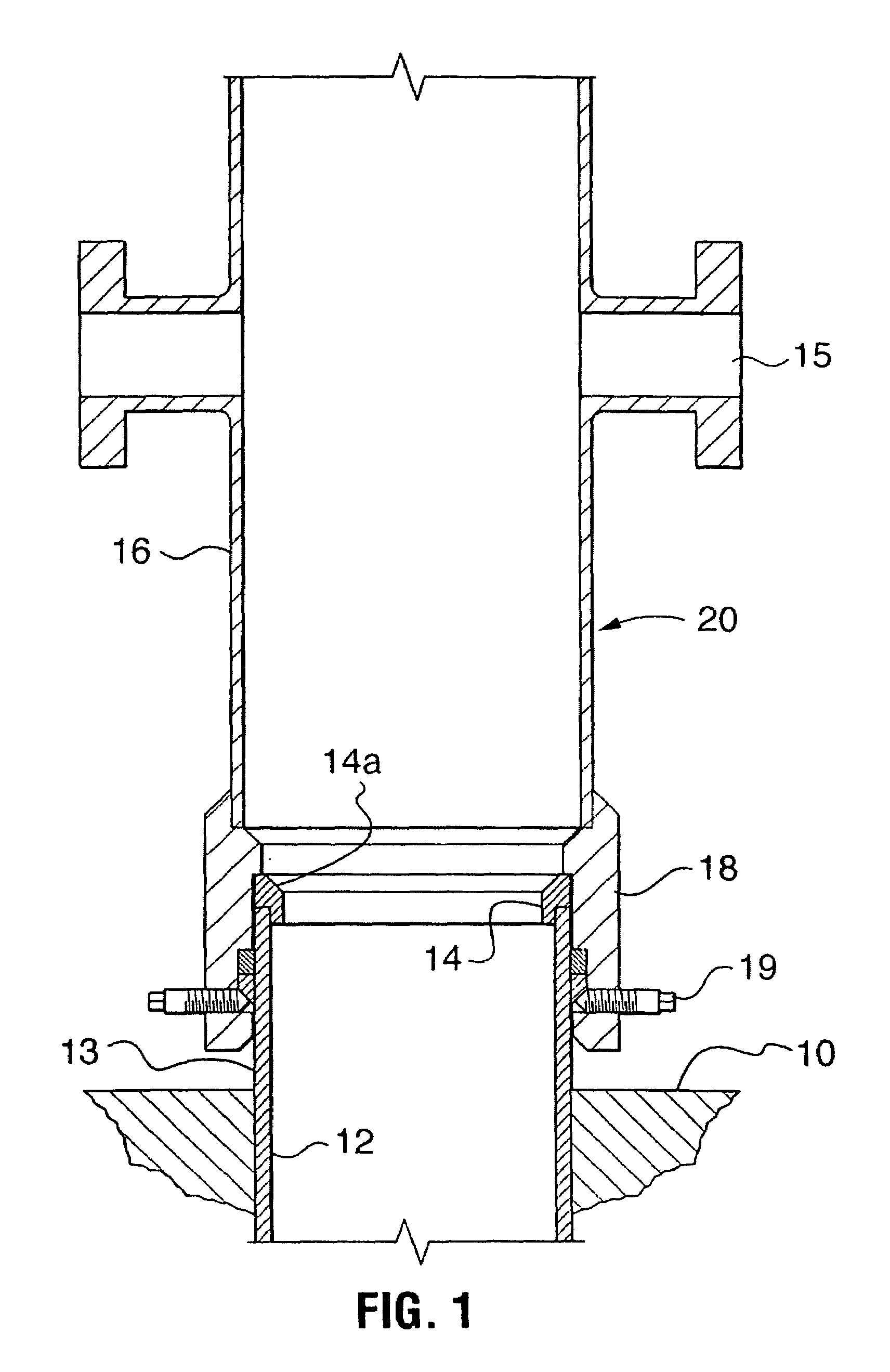
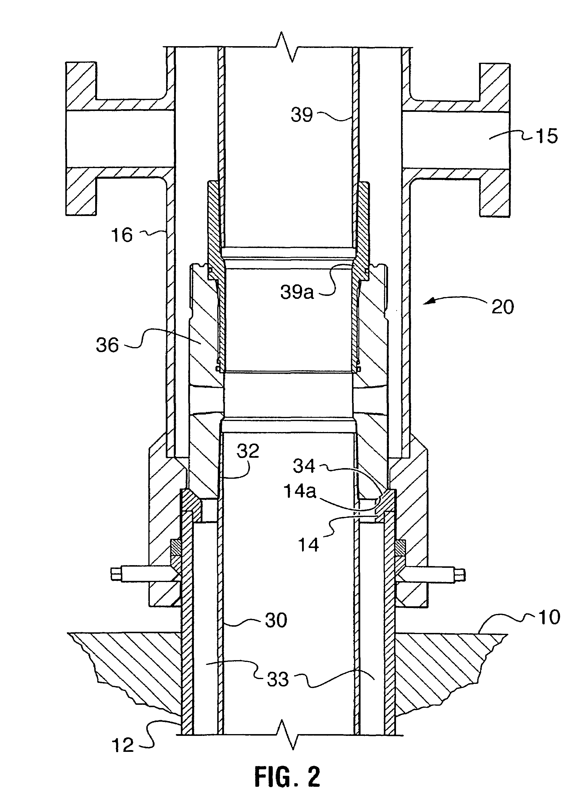
[0035]For the purposes of this specification, the expressions “wellhead system”, “tubular head”, “tubular string”, “mandrel”, and “threaded union” shall be construed in accordance with the definitions set forth in this paragraph. The expression “wellhead system” shall denote a wellhead (also known as a “casing head” or “surface casing head”) mounted atop a conductor assembly which is dug into the ground and which has, optionally mounted thereto, various Christmas tree equipment (for example, casing head housings, casing and tubing head spools, mandrels, hangers, connectors, and fittings). The wellhead system may also be referred to as a “stack” or as a “wellhead-stack assembly”. The expression “tubular head” shall denote a wellhead body such as a tubing head spool used to support a tubing mandrel, intermediate head spool (also known as a “B Section”) or a wellhead (also known as a casing head). The expression “tubular string” shall denote any casing or tubing, such as surface casing...


PUM


Abstract

A hybrid wellhead system is assembled using a plurality of threaded unions, such as spanner nuts or hammer unions, for securing respective tubular heads and a flanged connection for securing a flow control stack to a top of a tubing head spool. The tubing head spool is secured by a threaded union to an intermediate head spool. The intermediate head spool is secured by another threaded union to a wellhead. Each tubular head secures and suspends a tubular string in the well bore. The hybrid wellhead system is capable of withstanding higher fluid pressures than a conventional independent screwed wellhead, while providing a more economical alternative to a flanged, or ranged, wellhead system because it is less expensive to construct and faster to assemble.

Description

[0001]This application claims the benefit of priority under 35 U.S.C. §119(e) to U.S. Provisional Patent Application Ser. No. 60 / 513,142 filed Oct. 21, 2003.MICROFICHE APPENDIX[0002]Not Applicable.TECHNICAL FIELD[0003]The present invention relates generally to wellhead systems for the extraction of subterranean hydrocarbons and, in particular, to a hybrid wellhead system employing both threaded unions and flanged connections.BACKGROUND OF THE INVENTION[0004]Wellhead systems are used for the extraction of hydrocarbons from subterranean deposits. Wellhead systems include a wellhead and, optionally mounted thereto, various Christmas tree equipment (for example, casing and tubing head spools, mandrels, hangers, connectors, and fittings) The various connections joints and unions needed to assemble the components of the wellhead system are usually either threaded or flanged. As will be elaborated below, threaded unions are typically used for low-pressure wells where the working pressure i...

Claims


Application Information

Patent Timeline
Patent Type & Authority Patents(United States)
IPC IPC(8): E21B33/03E21B33/038E21B33/04
CPCE21B33/04E21B33/038E21B33/0422
Inventor MCGUIRE, BOBDALLAS, L. MURRAY
Owner WELLS FARGO BANK NAT ASSOC
Learn More