
Shock-absorbing handle for impact tool

a technology of impact tool and handle, which is applied in the field of hand tools, can solve the problems of user injury, rapid energy dissipation, and many potential problems of users of these types of tools, and achieve the effect of convenient and economical manufacture and assembly

Inactive Publication Date: 2005-05-12
CRAWFORD BRUCE ALLAN
View PDF15 Cites 10 Cited by
  • Summary
  • Abstract
  • Description
  • Claims
  • Application Information

AI Technical Summary

Benefits of technology

[0006] The present invention provides an impact tool that: temporarily stores the energy transferred to the tool by the impact of a hammer and then transfers the energy back to the tool instead of transferring the energy to the fingers, hand, wrist and arm, thus providing an aid in protecting the user from the potential injurious effects of shock and repetitive motion; helps protect the user's hand from injury in the event that a hammer blow either misses or glances off the intended point of impact on the proximal end of the tool a flange or expanded region above the grip portion of the handle; provides the user with a comfortable ergonomically designed gripping surface; is easy and economical to manufacture and assemble; and can either be designed and manufactured as a stand-alone aftermarket device that is attached with a conventional impact tool or integrated into the manufacturing process of the impact tool itself.
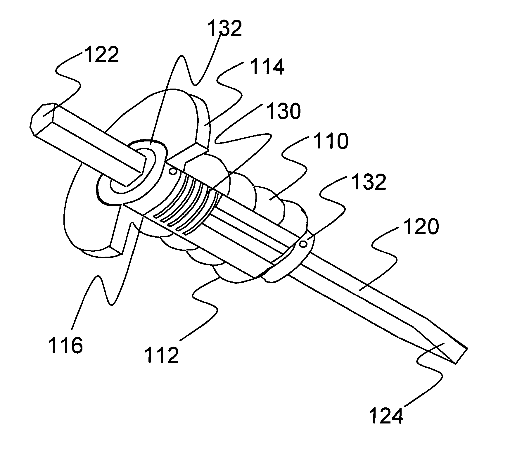
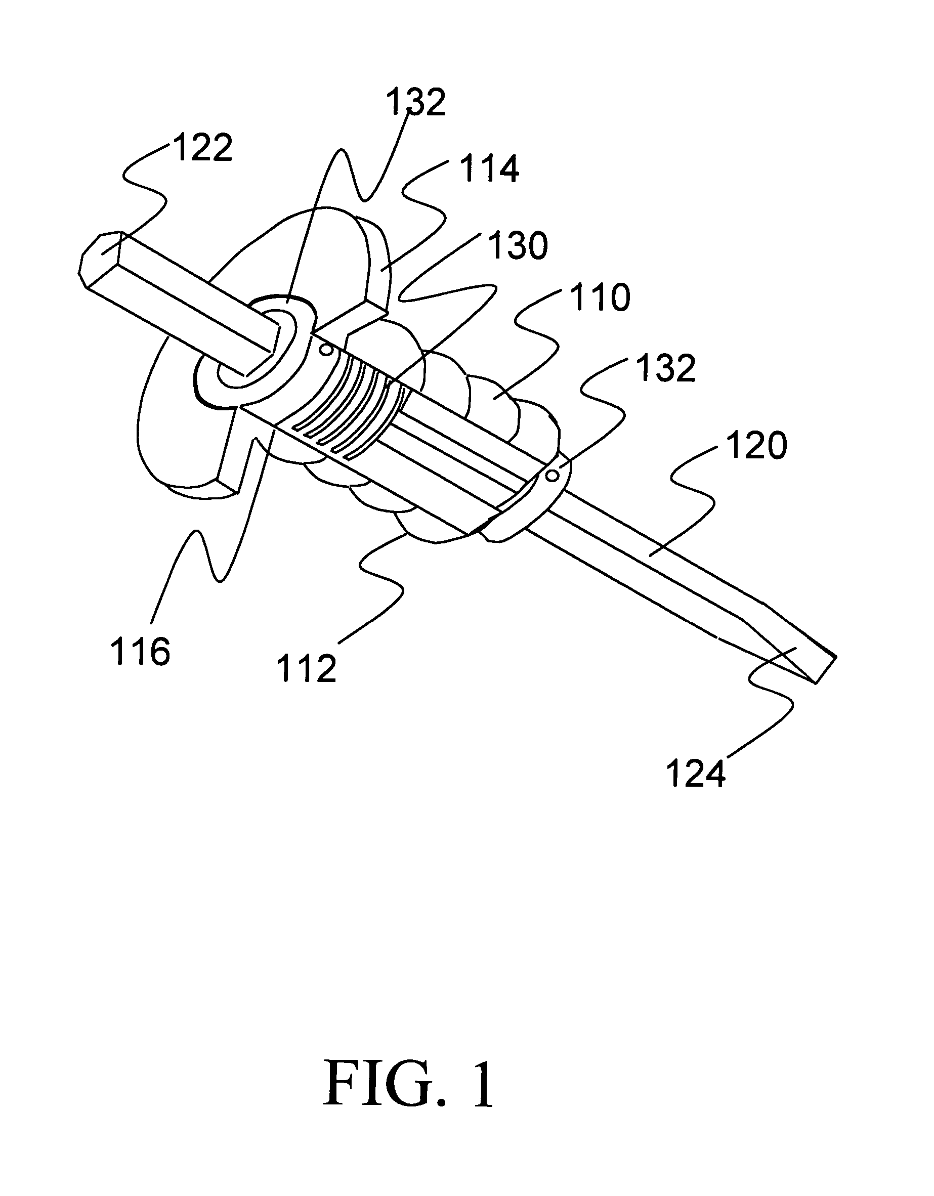
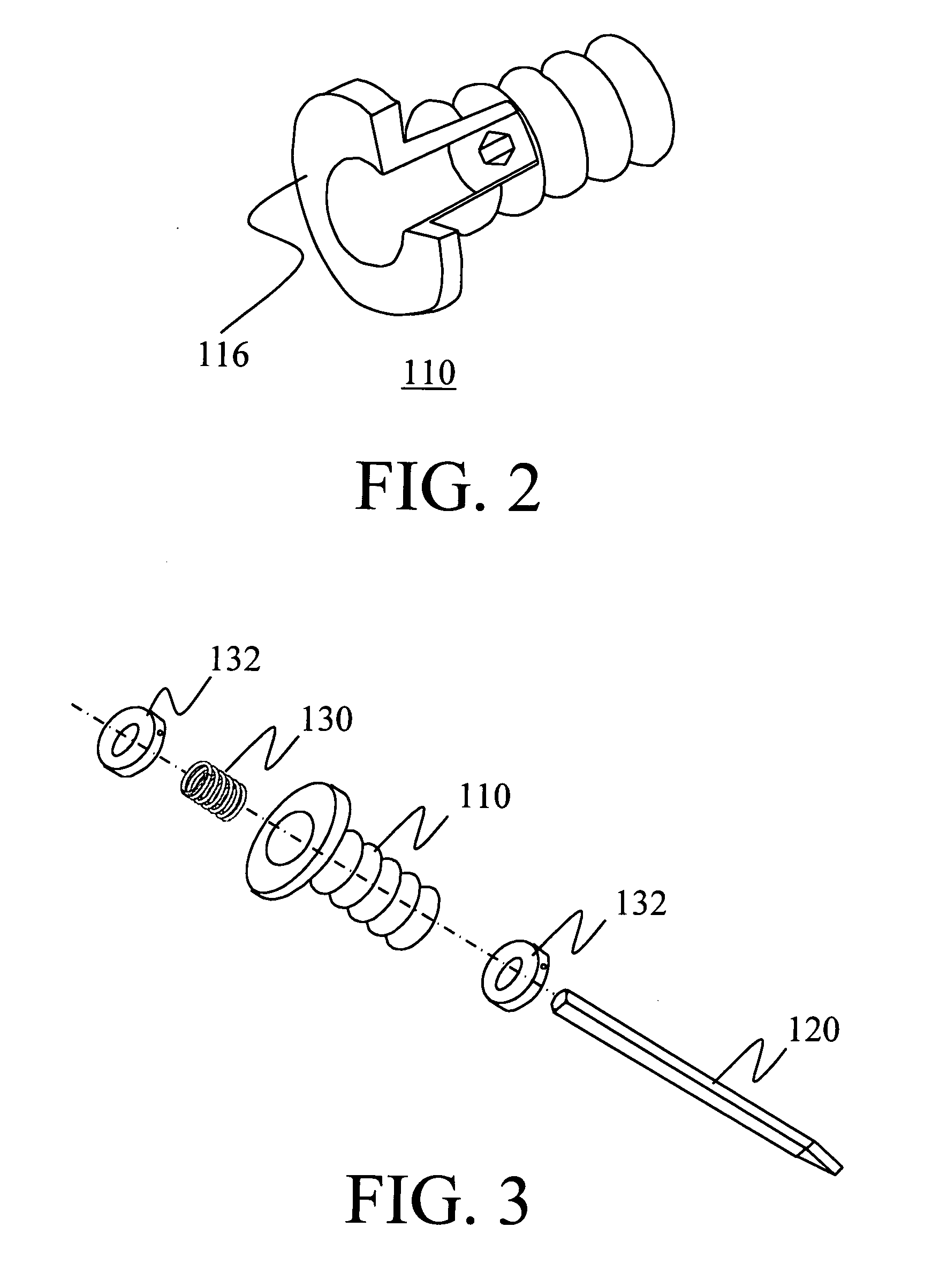
[0007] One embodiment of the present invention provides a shock-absorbing apparatus, which dampens the impact between a hand and an impact tool, with the shock-absorbing apparatus comprising a handle comprising a formed component that can be gripped in the hand and allow the impact tool movement within the handle; a shock-absorbing means disposed along an axis of the impact tool to provide a shock-absorbing function to the handle; and a stopping means disposed along an axis of the impact tool to limit the movement of the impact tool in relation to the handle.
[0008] In another embodiment of the present invention, the handle includes a flange extending from the upper region of the handle to provide protection from hand injury. In yet another embodiment of the present invention, the handle further includes a gripping surface on the exterior of the handle that cushions and enhances the grip and control of the impact tool. In another embodiment of the present invention, the formed component of the handle comprises the shock-absorbing means so as to allow the handle to provide the shock-absorbing function. In yet another embodiment of the present invention, the shock-absorbing means comprises a spring disposed along the axis of the impact tool to provide the shock-absorbing function to the handle. In still another embodiment of the present invention, the shock-absorbing means comprises a resilient material disposed along the axis of the impact tool to provide the shock-absorbing function to the handle. In yet another embodiment of the present invention, the shock-absorbing means comprises friction along the axis of the impact tool to limit the movement of the impact tool. In another embodiment of the present invention, the stopping means comprises a collar as part of the impact tool to limit the movement of the shock-absorbing means. In yet another embodiment of the present invention, the stopping means is incorporated into the design of the impact tool to limit the movement of the impact tool. In still another embodiment of the present invention, the stopping means comprises an aggregate on the proximal end of the impact tool to limit the movement of the impact tool. In another embodiment of the present invention, the stopping means comprises a resilient material disposed along the axis of the impact tool to limit the movement of the impact tool.

Problems solved by technology

Several potential problems and dangers exist for users of these types of tools.
The user subjected to this type of rapid energy dissipation from the tool into the body for long periods of time may suffer a whole host of injuries related to impact and repetitive motion.
Second, the surface upon which the hammer blows must fall for most of these types of tools is small in area.

Method used


Image

  • Shock-absorbing handle for impact tool
  • Shock-absorbing handle for impact tool
  • Shock-absorbing handle for impact tool

Examples


Embodiment Construction

[0016] The present invention relates to the field of impact tools. More specifically, this disclosure presents a shock-absorbing handle for impact tools. The following description is presented to enable one of ordinary skill in the art to make and use the invention and to incorporate it in the context of particular applications. Various modifications, as well as a variety of uses in different applications will be readily apparent to those skilled in the art, and the general principles defined herein may be applied to a wide range of embodiments. Thus, the present invention is not intended to be limited to the embodiments presented, but is to be accorded the widest scope consistent with the principles and novel features disclosed herein.

[0017] Overview of the Invention:

[0018] The present invention is a shock-absorbing handle. The shock-absorbing handle may be attached with or be incorporated into the design of typical chisels, punches, masonry drills and other such tools that are d...


PUM


Abstract

The present invention is a shock-absorbing apparatus that dampens the impact between a hand and an impact tool 120. The apparatus includes a handle 110 that can be gripped in the hand and allow the impact tool 120 movement within the handle 110. A shock-absorbing means 130 provides a shock-absorbing function to the handle 110. A stopping means 132 limits the movement of one end of the impact tool 120. The handle 110 may include a flange extending from the upper region of the handle 110 to provide protection from hand injury, and a gripping surface on the exterior of the handle 110 that cushions and enhances the grip and control of the impact tool 120.

Description

CROSS-REFERENCE TO RELATED APPLICATIONS [0001] This application claims the benefit of U.S. Provisional Application No. 60 / 519,036, filed with the U.S. Patent and Trademark Office on Nov. 8, 2003, and titled “Shock-Absorbing Handle for Impact Tool.”FIELD OF THE INVENTION [0002] The present invention relates to a hand tool that dampens the impact between a hand and an impact tool. BACKGROUND OF THE INVENTION [0003] Many tools exist that are designed to convert the impact of a hammer blow on one part of the tool into useable kinetic energy at the working or cutting end of the tool. These tools include all types of chisels, punches, drifts, impact drills, etc. and can, for example, be used to break bricks, chip concrete, cut through steel bars, create punch marks, drill holes and so forth by displacing material upon impact. [0004] Several potential problems and dangers exist for users of these types of tools. First, the user must grip the tool firmly in his hand in such a way as to guid...

Claims


Application Information

Patent Timeline
IPC IPC(8): B25G1/00B25G1/01F16F15/08
CPCB25G1/00Y10T16/48F16F15/08B25G1/01
Inventor CRAWFORD, BRUCE ALLAN
Owner CRAWFORD BRUCE ALLAN
Learn More