

Liquid crystal display device
a liquid crystal display and display device technology, applied in the field of liquid crystal display devices, can solve the problems of serious delay in response of the device, disadvantageous narrow viewing angle characteristics of the tn mode, and the inability of the mva-mode liquid crystal display device to be used in laptops requiring low power consumption, so as to reduce the effect of image burn
Inactive Publication Date: 2007-01-30
MERCK PATENT GMBH
View PDF12 Cites 554 Cited by
- Summary
- Abstract
- Description
- Claims
- Application Information
AI Technical Summary
Benefits of technology
The solution significantly reduces image burn and response delay, enhancing light transmission and display performance by using specific monomer compounds that align and polymerize liquid crystal molecules effectively, thereby minimizing image retention.
Problems solved by technology
Active matrix-type liquid crystal display devices have heretofore usually used a TN (twisted nematic) mode, but the TN mode is disadvantageously narrow in viewing angle characteristics.
Therefore, the MVA-mode liquid crystal display device cannot be employed for laptops requiring low power consumption.
However, if the distance between banks or ITO slits is significantly large, the propagation of liquid crystal molecule tilting takes much time and when a voltage is applied to the device for display, the response of the device is seriously delayed.
The generation of this image burn phenomenon is an unavoidable problem also in the liquid crystal display device produced by using the above-described technique of injecting a polymerizable monomer-containing liquid crystal material between substrates and polymerizing the monomer in the state of a voltage being applied, thereby memorizing the direction to which liquid crystal molecules turn over.
Method used
View moreImage
Smart ImageViewing Examples

Examples
example 1
[0032]A liquid crystal composition having added thereto 0.3 wt % of a diacrylate having functional groups bonded directly to the ring structure, represented by the following formula:
[0033]
was injected between opposing substrates of the liquid crystal display device and then, ultraviolet light was irradiated at 4 J / cm2 and at room temperature while applying a voltage of 10 V. The 48-hour image burn percentage of this liquid crystal display device was 6%.
Login to View More PUM
| Property | Measurement | Unit |
|---|---|---|
| voltage | aaaaa | aaaaa |
| size | aaaaa | aaaaa |
| voltage | aaaaa | aaaaa |
Abstract
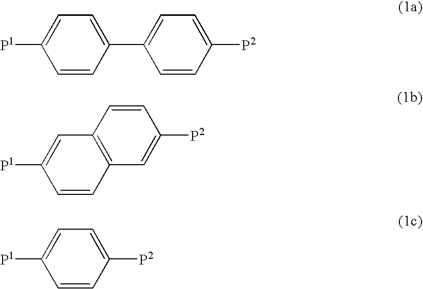
A liquid crystal display device produced through the steps of injecting a polymerizable monomer-containing liquid crystal composition between two substrates and, while applying a voltage between opposing transparent electrodes of the substrates, polymerizing the monomer, wherein the polymerizable monomer contained in the liquid crystal composition has one or more ring or condensed ring structures and functional groups bonded directly to the ring or condensed ring structure.The monomer is preferably represented by the following general formula:P1-A1-(Z1-A2)n-P2wherein P1 and P2 are acrylates or the like, A1 and A2 are 1,4-phenylenes or the like, Z1 is —COO— or the like, and n is 0 to 2.
Description
CROSS-REFERENCES TO RELATED APPLICATIONS[0001]This application is based upon and claims the benefit of priority from prior Japanese Patent Application No. 2002-113972, filed on Apr. 16, 2002, the entire contents thereof being incorporated herein by reference, and a continuation of PCT / JP03 / 04791 filed on Apr. 15, 2003.TECHNICAL FIELD[0002]The present invention relates to a liquid crystal display device using a liquid crystal orientation, the direction of which is determined by filling a liquid crystal material containing a photo- or heat-polymerizable monomer, oligomer or the like into between substrates, and polymerizing the polymerizable component while adjusting the voltage applied to the liquid crystal layer, and relates to such a liquid crystal material. The voltage applied includes 0 volts and hereinafter, the voltage adjustment should be understood to include 0 volts.BACKGROUND ART[0003]Active matrix-type liquid crystal display devices have heretofore usually used a TN (twist...
Claims
Login to View More Application Information
Patent Timeline
 Patent Type & AuthorityPatents(United States)
IPC IPC(8): C09K19/38C09K19/12C09K19/20C09K19/32C09K19/52G02F1/1337C08F2/00C08F20/18G02F1/13G02F1/1333G02F1/137G02F1/139
CPCC09K19/12C09K19/2007C09K19/322G02F1/133365G02F1/1393G02F1/133788C09K2019/0448C09K2019/548Y10T428/10G02F2001/133397G02F2001/13775Y10T428/1036G02F1/133707C09K2323/03C09K2323/00G02F1/133397G02F1/13775G02F1/13C09K19/34C09K19/38C08F2/00
InventorNAKANISHI, YOHEISHIBASAKI, MASAKAZUHANAOKA, KAZUTAKAINOUE, YUICHITARUMI, KAZUAKIBREMER, MATTHIASKLASEN-MEMMER, MELANIEGREENFIELD, SIMONHARDING, RICHARD
OwnerMERCK PATENT GMBH