
Permanent-magnet ground fault circuit interrupter plug and its permanent-magnet mechanism therein

a ground fault circuit interrupter, permanent magnet technology, applied in the direction of circuit-breaking switches, emergency protective arrangements for limiting excess voltage/current, coupling device connections, etc., can solve the problems of presenting potential hazards, gfci receptacles may not be suitable for certain situations, and certain components of gfcis such as a metal oxide varistor (hereinafter “mov”) often fail

Active Publication Date: 2007-01-30
CHEN HENG
View PDF18 Cites 21 Cited by
  • Summary
  • Abstract
  • Description
  • Claims
  • Application Information

AI Technical Summary

Benefits of technology

The solution provides an energy-saving, water-proof GFCI plug with a self-diagnosing function that effectively detects and responds to faults, reducing energy consumption and enhancing safety by minimizing electromagnetic force usage and ensuring continuous operation monitoring.

Problems solved by technology

However, the GFCI receptacles may not be suitable for certain situations, such as car-washing shops, and field construction sites where a wet condition may exist and mobile electrical equipments may be used.
Additionally, certain components of the GFCIs such as a metal oxide varistor (hereinafter “MOV”) often fail due to the exposure to the nature, for example, in extreme high and / or low temperatures.
It may present potential hazard if certain components of the GFCIs are failed.
Therefore, a heretofore unaddressed need exists in the art to address the aforementioned deficiencies and inadequacies.

Method used


Image

  • Permanent-magnet ground fault circuit interrupter plug and its permanent-magnet mechanism therein
  • Permanent-magnet ground fault circuit interrupter plug and its permanent-magnet mechanism therein
  • Permanent-magnet ground fault circuit interrupter plug and its permanent-magnet mechanism therein

Examples


Embodiment Construction

[0026]The present invention is more particularly described in the following examples that are intended as illustrative only since numerous modifications and variations therein will be apparent to those skilled in the art. Various embodiments of the invention are now described in detail. Referring to the drawings, like numbers indicate like parts throughout the views. As used in the description herein and throughout the claims that follow, the meaning of “a,”“an,” and “the” includes plural reference unless the context clearly dictates otherwise. Also, as used in the description herein and throughout the claims that follow, the meaning of “in” includes “in” and “on” unless the context clearly dictates otherwise.

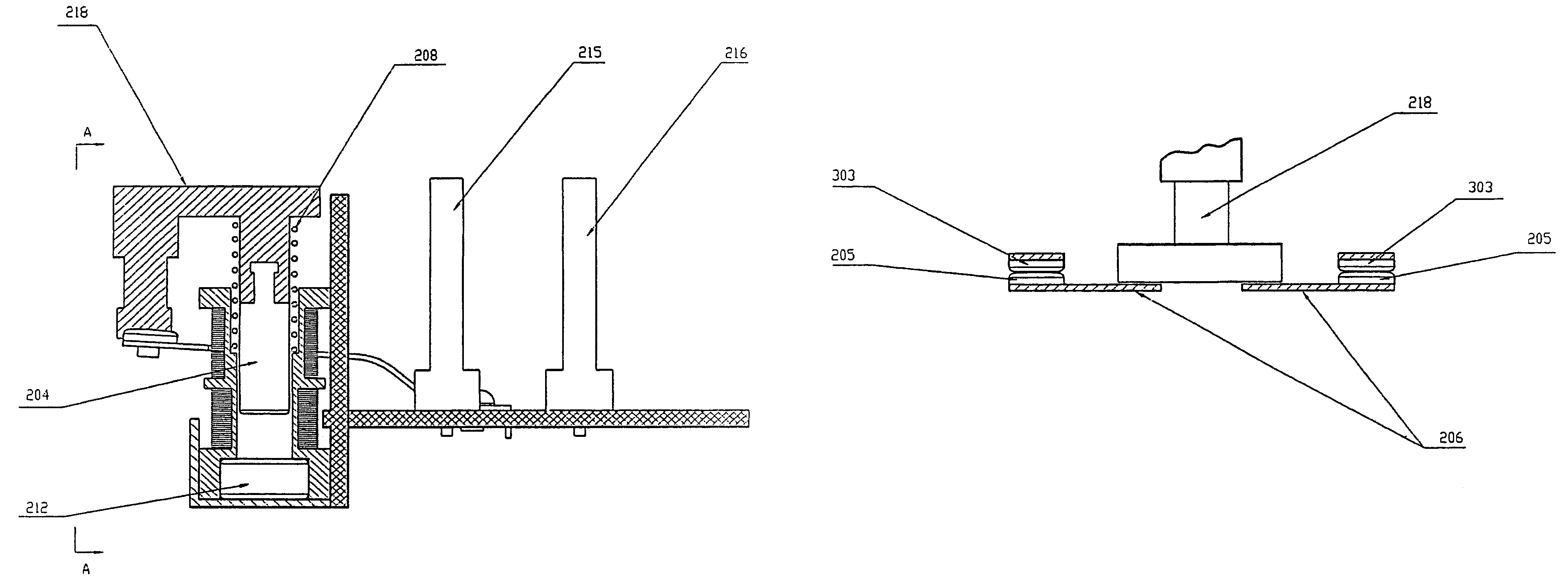
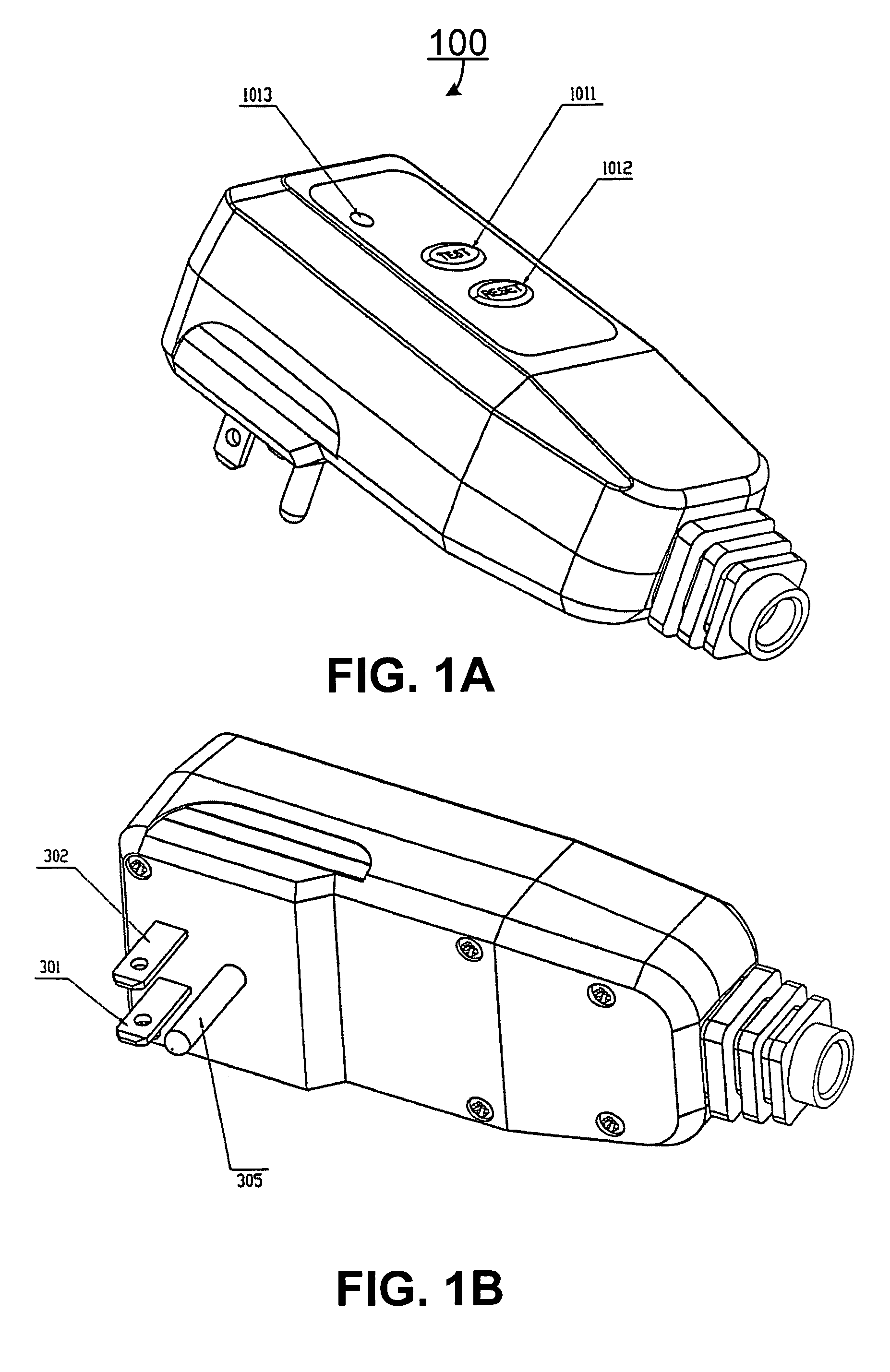
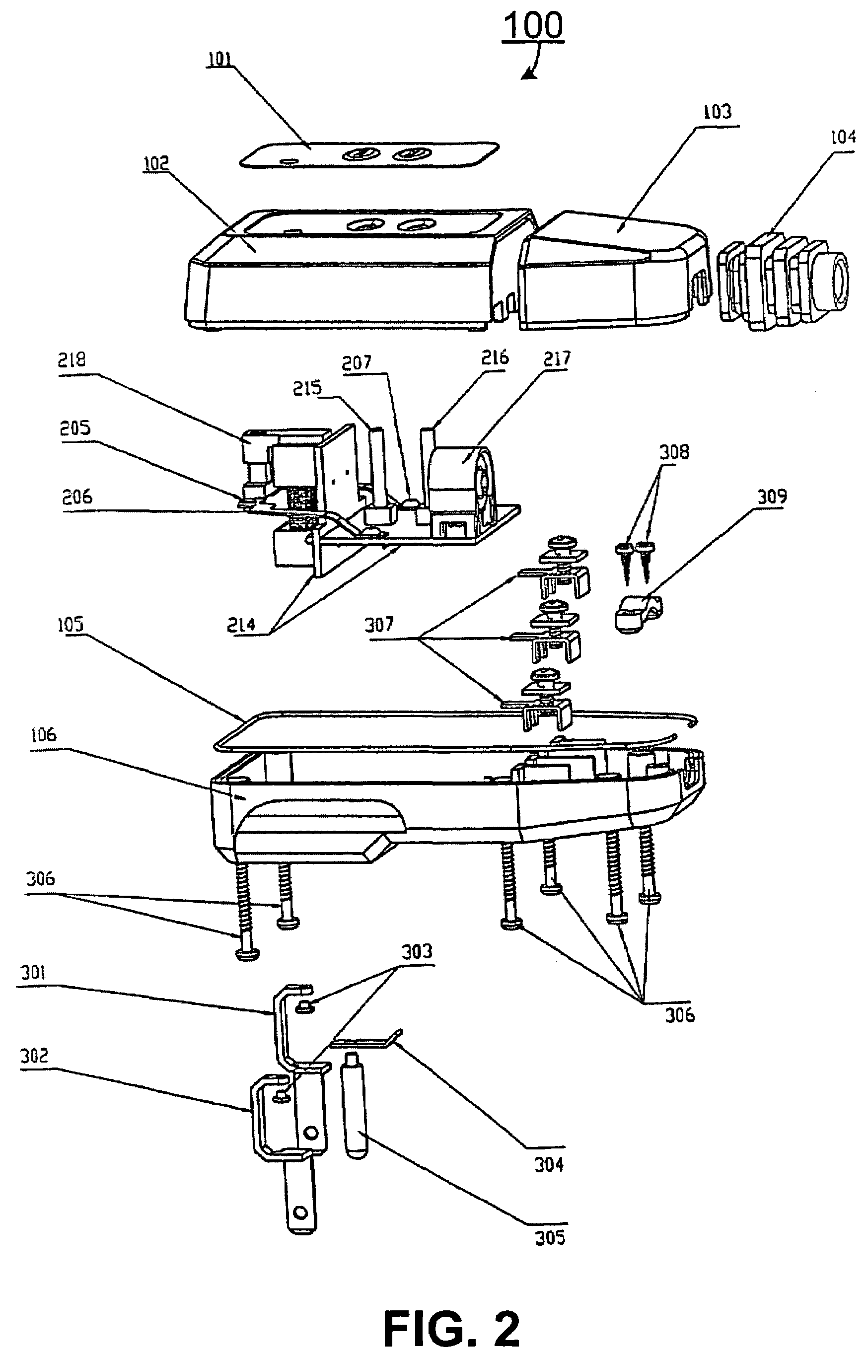
[0027]The description will be made as to the embodiments of the present invention in conjunction with the accompanying drawings 1–7. In accordance with the purposes of this invention, as embodied and broadly described herein, this invention, in one aspect, relates to an energy-...


PUM


Abstract

A permanent-magnet ground fault circuit interrupter plug with self-diagnosing function having an enclosure and a permanent-magnet mechanism encased in the enclosure. In one embodiment, the permanent-magnet mechanism includes a frame assembly having a crossbeam, a frame pressure post and a core connecting post positioned at each side of the crossbeam, a core attached to the core connecting post and positioned inside a coil assembly, a spring sleeved on the core connecting post and positioned therebetween an inner cam of the coil assembly and the crossbeam of the frame assembly; a circuit-breaking coil and a circuit-connecting coil wound on the coil assembly, respectively, a permanently magnet positioned proximately to the core, a pair of movable contact arms with each having one movable contact positioned at each lateral side of the frame pressure post for communicating with the frame assembly, a pair of fixed contacts positioned above the corresponding movable contacts, and a metal oxide varistor with one end electrically connected to a first terminal of a power source directly and the other end electrically connected to a second terminal of the power source from a load side across a circuit breaker.

Description

FIELD OF INVENTION[0001]The present invention generally relates to a ground fault circuit interrupter (hereinafter “GFCI”), and in particularly to a permanent-magnet GFCI in the form of plugs with a permanent-magnet mechanism applicable to GFCIs in general, current-leakage interrupters and other circuit fault protective devices.BACKGROUND OF THE INVENTION[0002]Most of GFCIs on the market are in the form of receptacles. Such GFCI receptacles are generally adapted for securely mounting on walls of a building. However, the GFCI receptacles may not be suitable for certain situations, such as car-washing shops, and field construction sites where a wet condition may exist and mobile electrical equipments may be used.[0003]Although there are several types of GFCI plugs on the current market, they all rely on an electromagnetic coil to produce an electromagnetic force to maintain the GFCI plugs in its “ON” state when powered. When a circuit fault occurs, an integrated circuit (hereinafter “...

Claims


Application Information

Patent Timeline
Patent Type & Authority Patents(United States)
IPC IPC(8): H01H9/00H02H3/00
CPCH01H89/08H01H83/04H01H51/12H01H51/2209H02H9/042H01R13/5205
Inventor CHEN, WUSHENGDAI, YONGLI, XIAOYONG
Owner CHEN HENG
Learn More