

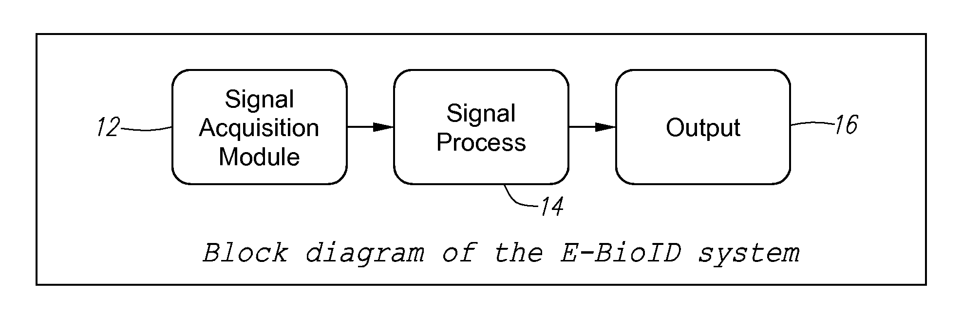
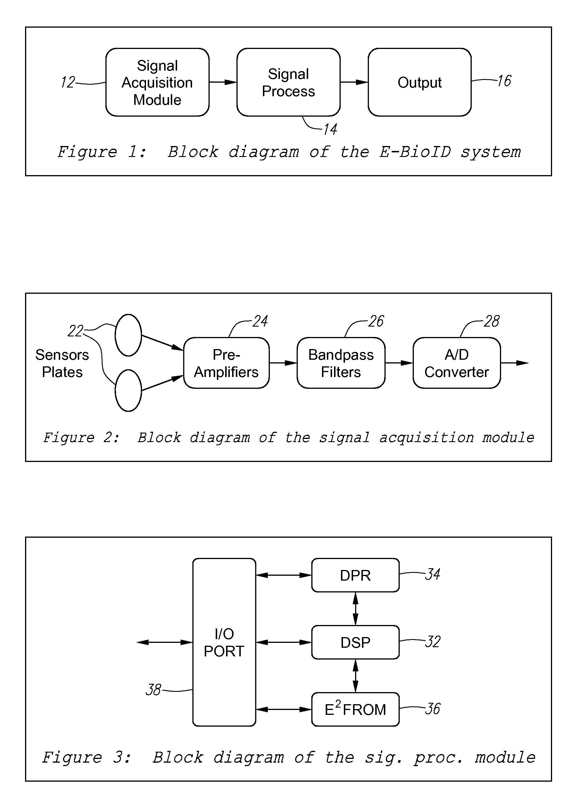
Method and apparatus for electro-biometric identity recognition
a technology of electrobiometric identity and identification method, applied in the field of electrobiometric identification and verification system, can solve the problems of operator attendance, imposing a substantial burden on users, and limited market penetration of technology
- Summary
- Abstract
- Description
- Claims
- Application Information
AI Technical Summary
Benefits of technology
Problems solved by technology
Method used
Image

Examples
example
Recognition Algorithm
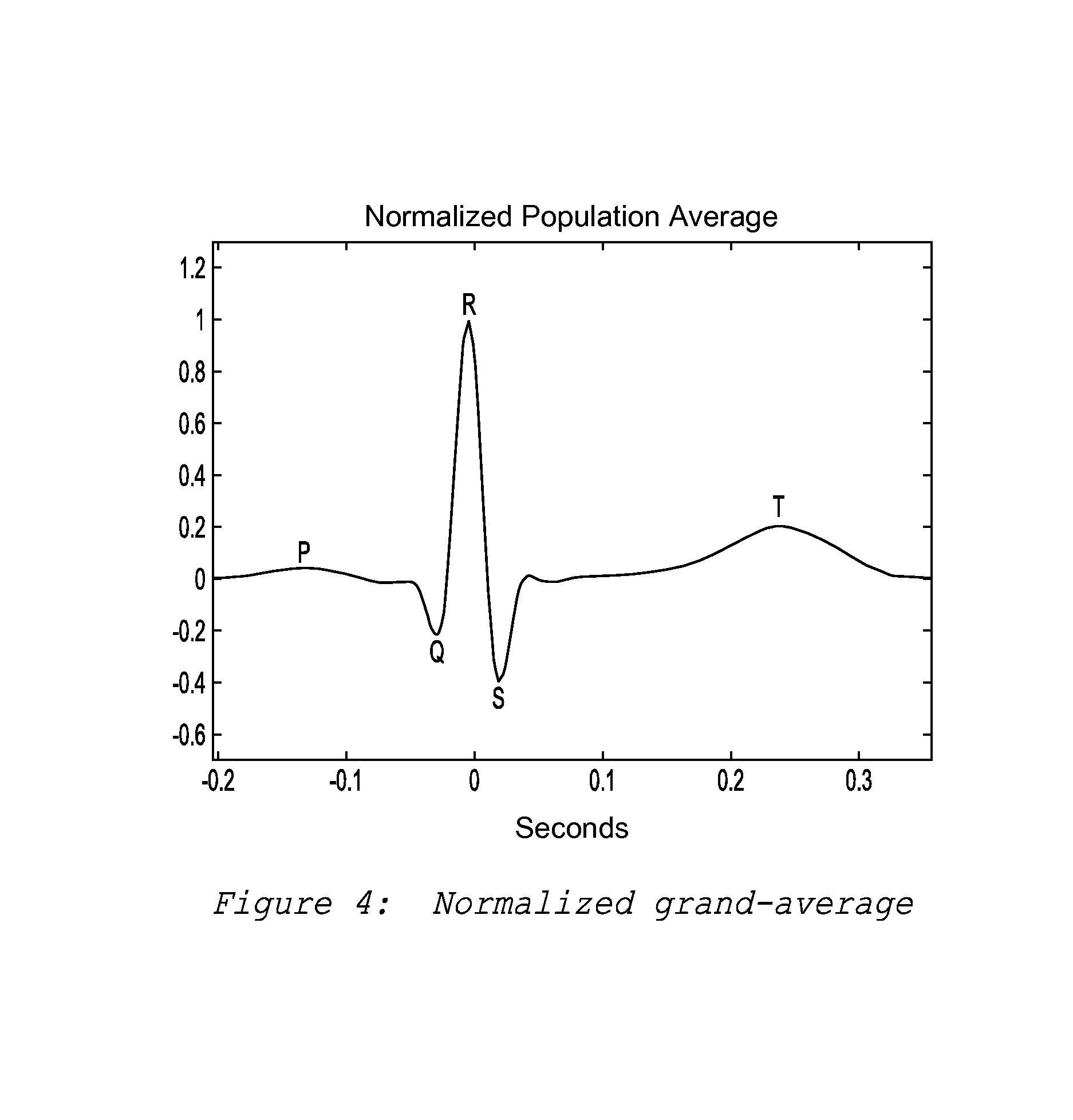
[0078]The following is an example an algorithm for the recognition phase:[0079]i. Let xj(n) represent a 10-second, 250 Hz digitized sample of the tested subject.[0080]ii. xj(n) is band-pass filtered in the range 4 Hz–40 Hz.[0081]iii. The filtered signal is denoted yj(n).[0082]iv. The filtered signal yj(n) is searched for the locations of QRS complexes, using the R peak as an anchor point.[0083]v. The filtered signal yj(n) is maintained or inverted to obtain positive ‘R’ peaks.[0084]vi. The identified QRS complexes are counted to establish an average pulse rate reading PRj.[0085]vii. The filtered signal yj(n) is segmented around the anchor points, taking 50 samples before and 90 samples after each anchor point.[0086]viii. The segments are aligned around the anchor points and averaged to produce the subject electro-cardiologic signal, denoted sj(n).[0087]ix. The subject electro-cardiologic signal sj(n) is normalized according to the average pulse rate PRj. The pul...
PUM
 Abstract
Description
Claims
Application Information