Soft tissue anchor and method of using same

Active Publication Date: 2007-02-13
DEPUY SYNTHES PROD INC
View PDF21 Cites 126 Cited by
  • Summary
  • Abstract
  • Description
  • Claims
  • Application Information

AI Technical Summary

Benefits of technology

[0007]Upon installation of the soft tissue anchor device, the soft tissue anchor device attaches a soft tissue to a hard tissue and

Problems solved by technology

However, as the device is tightened, the tissue tends t

Method used


Image

  • Soft tissue anchor and method of using same
  • Soft tissue anchor and method of using same
  • Soft tissue anchor and method of using same

Examples


Embodiment Construction

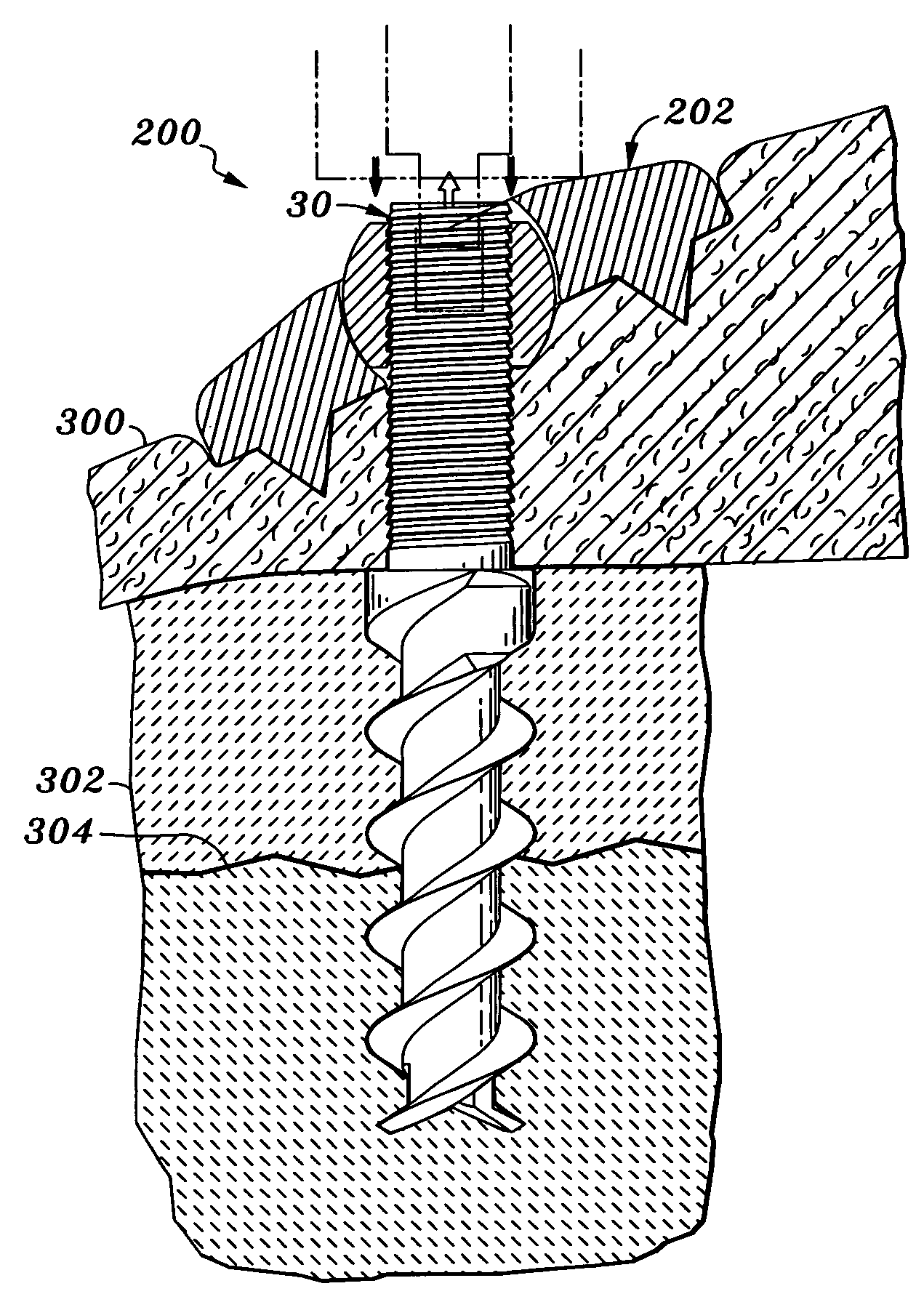
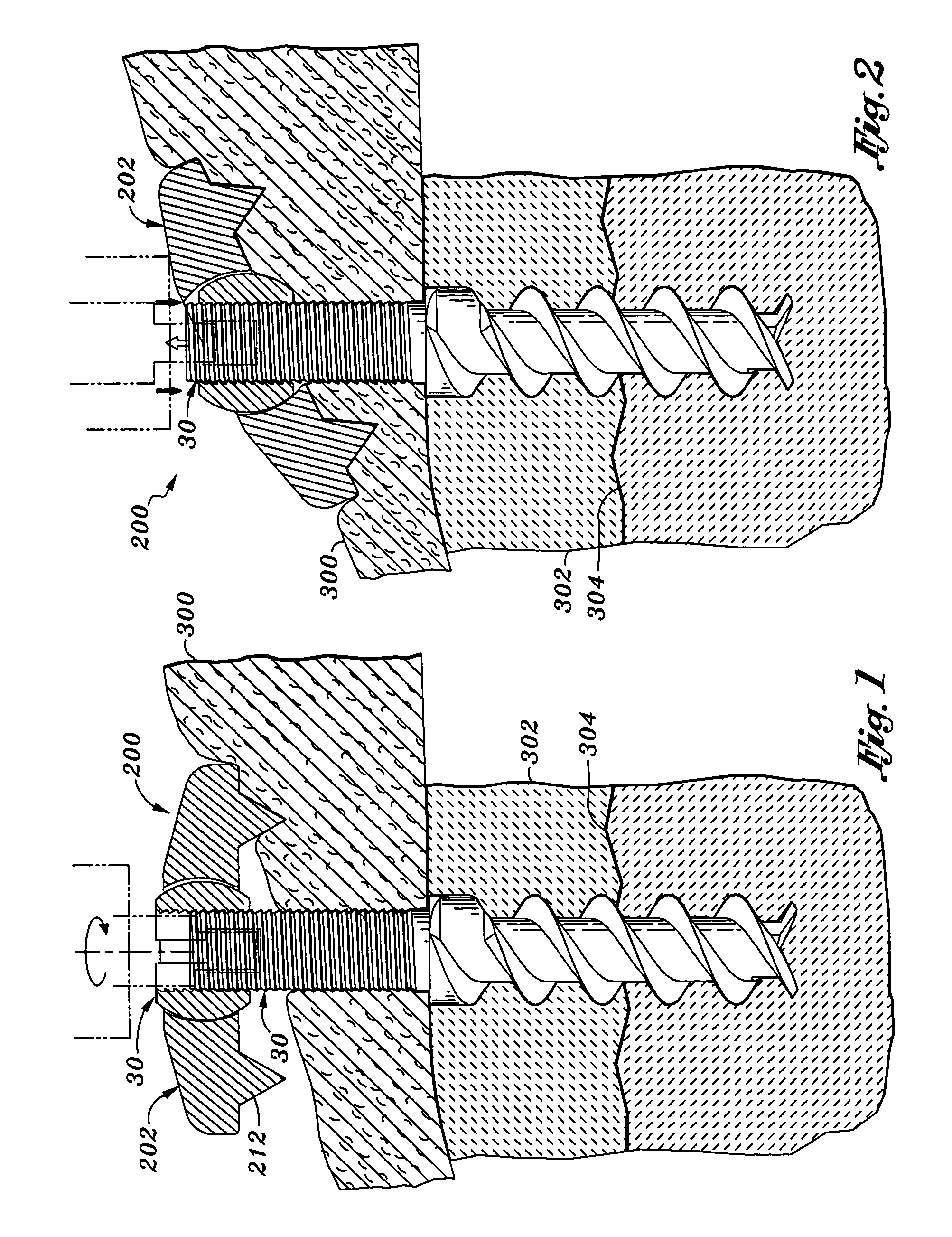
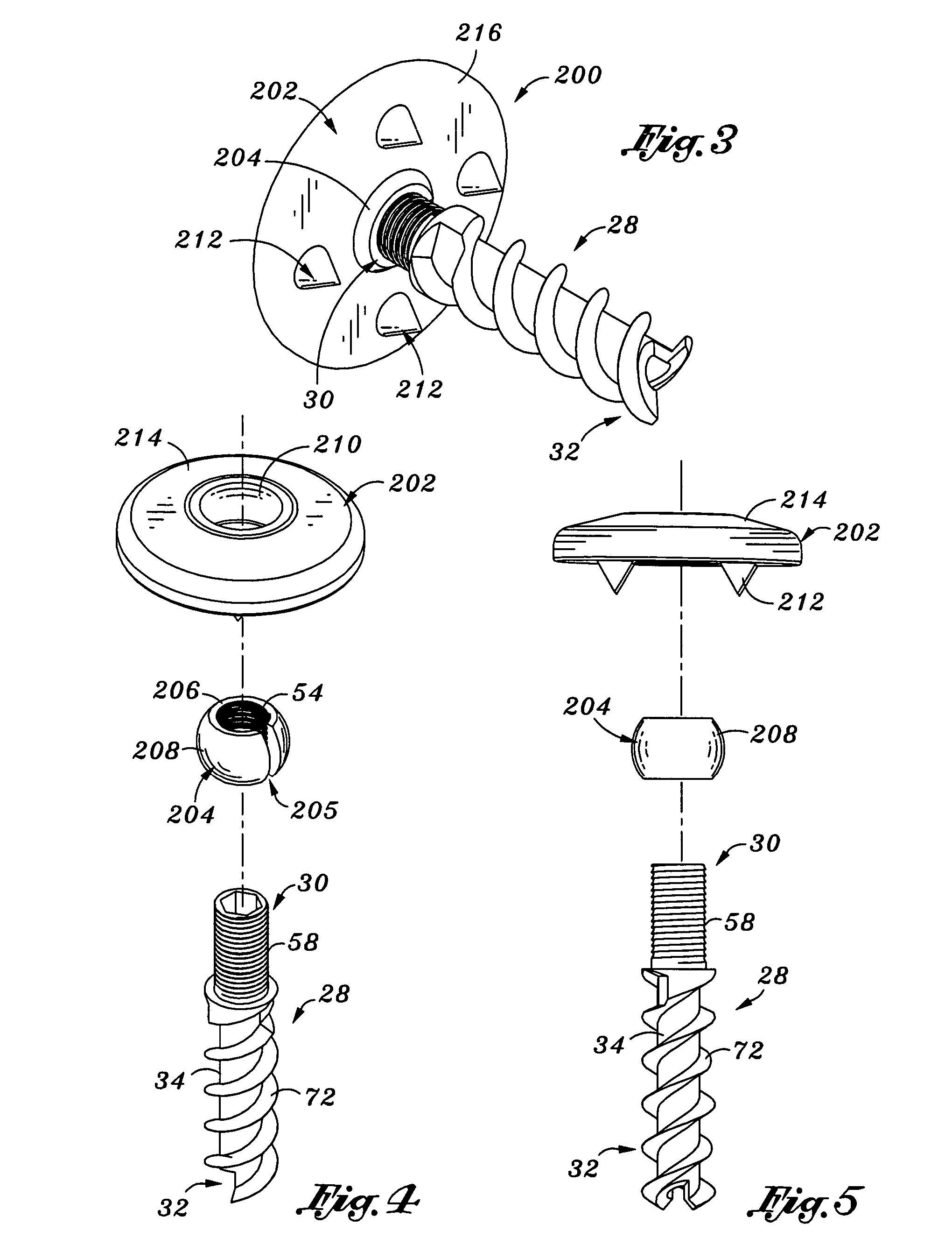
[0028]Referring now to the drawings wherein the showings are for purposes of illustrating preferred embodiments of the present invention only, and not for purposes of limiting the same, a soft tissue fixation device 200 is shown. FIG. 1 illustrates the fixation device 200 as installed (i.e., after placement attaching tissue to a bone). After installation, the fixation device 200 can be compressed and / or the flange 202 rotated (i.e., angled) as shown in FIG. 2. When the flange is compressed, it is retained in position such that the device does not move either distally or proximally. The length of the fixation device 200 is variable depending on the amount of compression used. Preferably, the compression is performed via ratcheting rather than rotation to avoid rotation of the tissue. As described more fully later, this compression can be performed using a ratcheting tool, such as the one shown in FIG. 8 or the one shown in FIGS. 9A and 9B. The fixation device 200 includes an adjustab...


PUM


Abstract

A soft tissue anchor device and methods of installing the soft tissue anchor device are disclosed. The device has an elongate body having a proximal end and a distal end. There is a helical anchor on the distal end. A retention structure is provided on the body, proximal to the anchor. The device also includes a proximal anchor, moveably carried by the body. The device includes an adjustable flange that is configured to receive the proximal anchor. The proximal anchor is configured to be rotational with respect to the flange. The adjustable flange is configured to be positioned at a variable angle with respect to the body. The proximal anchor is moveable in the distal direction with respect to the body and the retention structure resists proximal movement of the proximal anchor with respect to the body.

Description

CROSS-REFERENCE TO RELATED APPLICATIONS[0001]This application claims the benefit of U.S. Provisional Application 60 / 428,847, filed Nov. 25, 2002, the entire contents of which are hereby incorporated by reference.STATEMENT RE: FEDERALLY SPONSORED RESEARCH / DEVELOPMENT[0002]Not ApplicableBACKGROUND OF THE INVENTION[0003]The present invention relates generally to surgical devices and more particularly to a soft tissue anchor with an axially moveable and locking flange and methods of using same.[0004]A variety of elongated implants (nail, screw, pin, etc.) have been developed to attach soft tissue (e.g., a ligament or a tendon) to hard tissue (e.g., a bone). The elongated implants may be secured with sutures. Typically, such devices attach the tissue to the bone by rotating the fixation device until the tissue is firmly fixed to the bone. However, as the device is tightened, the tissue tends to rotate, particularly with the final tightening cinch.[0005]Thus, there is a need for a fixatio...

Claims


Application Information

Patent Timeline
IPC IPC(8): A61B17/58A61B17/04A61B17/86A61F2/08
CPCA61B17/0401A61F2/0811A61B17/8695A61B2017/0409A61B2017/044A61F2002/0888A61F2002/0829A61F2002/0858A61F2/0805
Inventor CULBERT, BRAD S.
Owner DEPUY SYNTHES PROD INC
Why Eureka
Try Eureka