Fuse unit

a technology of fuse unit and fuse, which is applied in the direction of substation/switching arrangement casing, coupling device connection, contacts, etc., can solve the problems of cumbersome removal or loosening of the same, and achieve the effect of easy and visual inspection of the fusible parts, easy and visual inspection, and easy and visual inspection

Active Publication Date: 2007-02-13
YAZAKI CORP
View PDF31 Cites 52 Cited by
  • Summary
  • Abstract
  • Description
  • Claims
  • Application Information

AI Technical Summary

Benefits of technology

[0009]The present invention is developed in view of the above-described problem, and it is therefore an object of the invention to provide a fuse unit in which the states of fusible portions of the fuse unit attached to the battery side can be easily checked when the fuse units are superposed in a direction away from a battery.
[0037]According to the invention, since the shapes of cavities differ from each other in respective housings, it becomes possible to easily and visually check both fusible portions even in a case where the fusible portion of the battery side fuse unit and the fusible portion of the forward fuse unit overlap each other.

Problems solved by technology

That is, such a problem arises, by which it is very cumbersome to remove or loosen the same.

Method used


Image

  • Fuse unit
  • Fuse unit
  • Fuse unit

Examples


first embodiment

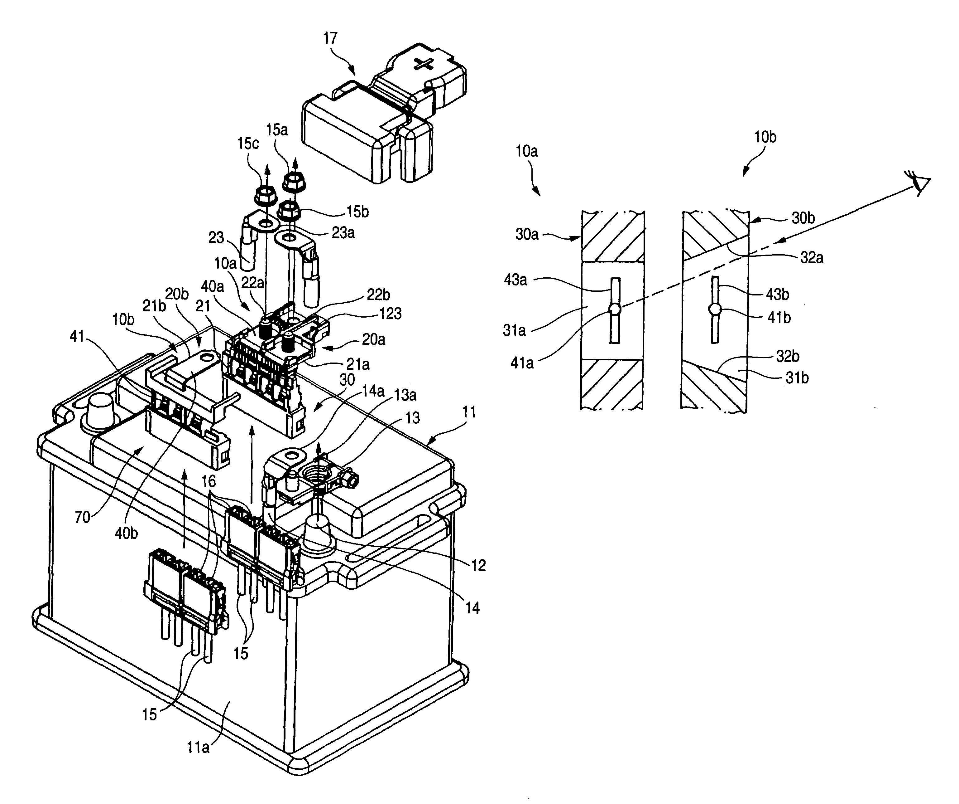
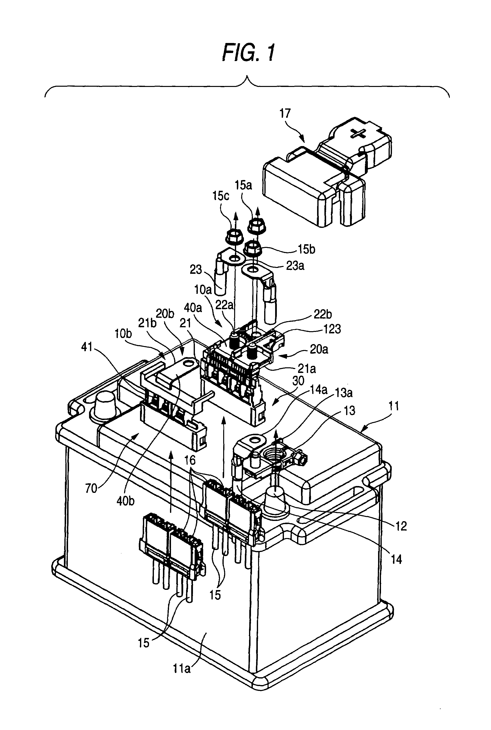
[0059]FIG. 4 is a front view of the first housing 30a and the second housing 30b of the invention. However, the first housing 30a is hidden behind the second housing 30b. Cavities 31, which are made open to the front side and are internal spaces, are disposed side by side in the housing 30b. A fuse 43 serving as a fusing body having a fusible portion 41 is provided at the position corresponding to the cavity 31 in the fuse body 40b, the battery 11 side and the connector 42 side in the fuse body 40 are electrically connected to each other via the fuse 43.

[0060]Also, the fuse bodies 40a and 40b are made integral with each other at the battery post 12 side from the fuse 43, but are electrically separated from each other at the connector 42 side and further extend, thereby individually forming connectors 42 independently.

[0061]In addition, when producing the fuse units 10a and 10b, the fuse bodies 40a and 40b each including a fuse 43 having a fusible portion 41 at a predetermined positi...

second embodiment

[0064]FIG. 6 is a front view showing a case where the battery side fuse and the forward fuse are shifted in relation to each other according to the invention. FIG. 7A is a front view showing arrangement of the battery side fuse, and FIG. 7B is a front view showing arrangement of the forward fuse.

[0065]As shown in FIG. 7A and FIG. 7B, by shifting the positions of the fuses 43a and 43b in the cavities 31a and 31b, the fusible portion 41a of the first fuse unit 10a and the fusible portion 41b of the second fuse unit 10b are disposed so that the fuses 43a and 43b do not overlap each other. As a result, as shown in FIG. 6, the fuse units 10a and 10b are observed from the front side, it is possible to visually check the fusible portions 41a and 41b at the same time through the forward cavity 31b.

[0066]Also, in this case, the fusible portions 41a and 41b may be provided at the center position of the fuses 43a and 43b. Also, as in the case shown in FIG. 4 and FIG. 5, the fusible portions 4...

third embodiment

[0067]FIG. 8A and FIG. 8B show a case where the positions of the cavities 31a and 31b are shifted with respect to the housings 30a and 30b according to the invention.

[0068]In this case, the housings 30a and 30b, in which the sizes of the cavities 31a and 31b, sizes and shapes of the fuses 43a and 43b, and arrangement of the cavities 31a and 31b are identical to each other, are disposed so as to overlap each other. Since the positions of the fuses 43a and 43b are shifted by shifting the positions of the cavities 31a and 31b with respect to the housings 30a and 30b in the horizontal direction although the positions of the housings 30a and 30b are the same, the fusible portions 41a and 41b are shifted so as not to overlap each other. Therefore, it is possible to visually check the fusible portion 41a of the first fuse unit 10a and the fusible portion 41b of the second fuse unit 10b in view from the front side.


PUM


Abstract

A fuse unit includes first and second fuse devices. Each of the fuse devices includes a attaching portion to be attached to a battery terminal of a battery, a housing provided on the attaching portion and having a cavity which is opened forward and backward of the housing, and a fuse body having a first end which is electrically connected to the battery terminal and a second end which is covered with the housing to form a wire connection part, the fuse body having a fusible portion which is disposed in the cavity. When the housings are superposed in a direction away from the battery, at least one of the housings and the fuse bodies are constructed so that the fusible portions are checked as viewed in a forward direction of the housings.

Description

BACKGROUND OF THE INVENTION[0001]The present invention relates to a fuse unit, for example, a fuse unit connected to a battery of a vehicle.[0002]Recently, such a fuse unit as shown in FIG. 14 has been disclosed (For example, refer to JP-A-2002-329457 (FIG. 9)).[0003]As shown in FIG. 14, the fuse unit 100 connects a battery 101 and an electric wire 111 for supplying power to each other, and includes a conductive metal plate fuse element 118 having fuses 114 and 116, and an insulative resin body 117 in which the fuse element 118 is inserted and molded. The resin body 117 has a front side divided body 113 and a rear side divided body 115. Both the divided bodies 113 and 115 are folded at a right angle. A fuse 114 for connecting a connection portion 104 of a battery terminal 102 and an alternator terminal 106 is disposed on the front side divided body 113. Four fuses 116 are disposed in parallel to each other on the rear side divided body 115, and four tab terminals 120 are formed at t...

Claims


Application Information

Patent Timeline
Patent Type & Authority Patents(United States)
IPC IPC(8): H01H85/08H01H69/02H01H85/044H01R4/28H01H85/30
CPCH01H85/044H01H85/30H01H2085/025H01H2001/5877
Inventor IWATA, MASASHI
Owner YAZAKI CORP
Why Eureka
Try Eureka