Dual-opening mechanism of door

a dual-opening and door technology, applied in the direction of wing accessories, casings/cabinets/drawers details, manufacturing tools, etc., can solve the problems of limited placement and orientation of cabinet installation

Inactive Publication Date: 2007-02-20
TAKIGEN MFG CO LTD
View PDF23 Cites 40 Cited by
  • Summary
  • Abstract
  • Description
  • Claims
  • Application Information

AI Technical Summary

Benefits of technology

[0004]The present invention aims to solve the above problems of the prior art. It is an object of the present invention to provide a dual-opening mechanism of a door which enables the door to be opened from either the left or right side, which allows arbitral position and orientation of cabinet installation, which, even when there is an obstacle on the right or left side of the door, allows the door to be opened freely from the other side, and which enables the hinge to serve also as a lock device.
[0013]With such a structure, the door may be locked by coupling each of the first and second pairs of moving hinge parts to each of the first and second pairs of stationary hinge parts with each of the first and second pairs of hinge pins in the opposite sides of the door. From this locked state, by selectively operating either one of the first and second handles to draw either one of the first and second pairs of hinge pins out of the corresponding one of the first and second pairs of hinges, the door may be opened / closed by pivoting around the other of the first and second pairs of hinge pins coupled to the corresponding other of the first and second pairs of hinges. Thus the door may be opened from either the left or right side when the dual-opening mechanism of a door is provided in the left and right sides of the door. Alternatively, the door may be opened from either the upper or lower side when the dual-opening mechanism of a door is provided in the upper and lower sides of the door. This allows arbitral position and orientation of the cabinet installation, and even when there is an obstacle on the right or left side, or the upper or lower side of the door, the door may still be opened freely from the other side. The hinges may also be used as locking means for the door.
[0016]With this structure, when the door is opened, the hinge knuckles of the moving hinge part may be released from the hinge knuckle of the stationary hinge part. In this motion, the beveled guide portions on the hinge knuckles eliminate friction between the hinge knuckles to facilitate extraction of the hinge knuckle of the stationary hinge part from between the hinge knuckles of the moving hinge part. When the door is closed, the hinge knuckle of the stationary hinge part is fitted between the hinge knuckles of the moving hinge part. In this motion, the beveled guide portions on the hinge knuckles eliminate friction between the hinge knuckles, lead the hinge knuckle of the stationary hinge part into the position between the hinge knuckles of the moving hinge part, and facilitate coupling of the stationary hinge part to the moving hinge part, with the axes of the hinge knuckles of the stationary and moving hinge parts being aligned.
[0018]With this structure, increase in sliding resistance may be prevented, which is caused by frictional rattling or galling between the hinge pins and the hinge knuckles of the stationary and moving hinge parts upon insertion and removal of the hinge pins with respect to the knuckles.
[0020]With this structure, even when the door is very heavy and when opened, hangs down out of alignment with the casing, the follower part on the door side is guided by the guide part on the casing side in closing the door, and accordingly, the door may be led into the right position on the face of the casing having the opening. With this positional adjustment of the door, the moving hinge part may securely be aligned with the stationary hinge part, and the hinge pins may be inserted into the hinge parts securely and smoothly.
[0021]According to the dual-opening mechanism of a door according to the present invention, by providing the dual-opening mechanism of a door in the left and right sides of a door, the door may be opened from either the left or right side, and by providing this mechanism in the upper and lower sides of a door, the door maybe opened from either the upper or lower side. This allows arbitral position and orientation of the cabinet installation, and even when there is an obstacle on the right or left side, or the upper or lower side of the door, the door may still be opened freely from the other side. The hinges may also be used as locking means for the door.

Problems solved by technology

However, the conventional cabinet door is opened / closed from only one side, left or right, and the position and orientation of cabinet installation are limited by the side from which the door is opened.

Method used


Image

  • Dual-opening mechanism of door
  • Dual-opening mechanism of door
  • Dual-opening mechanism of door

Examples


Embodiment Construction

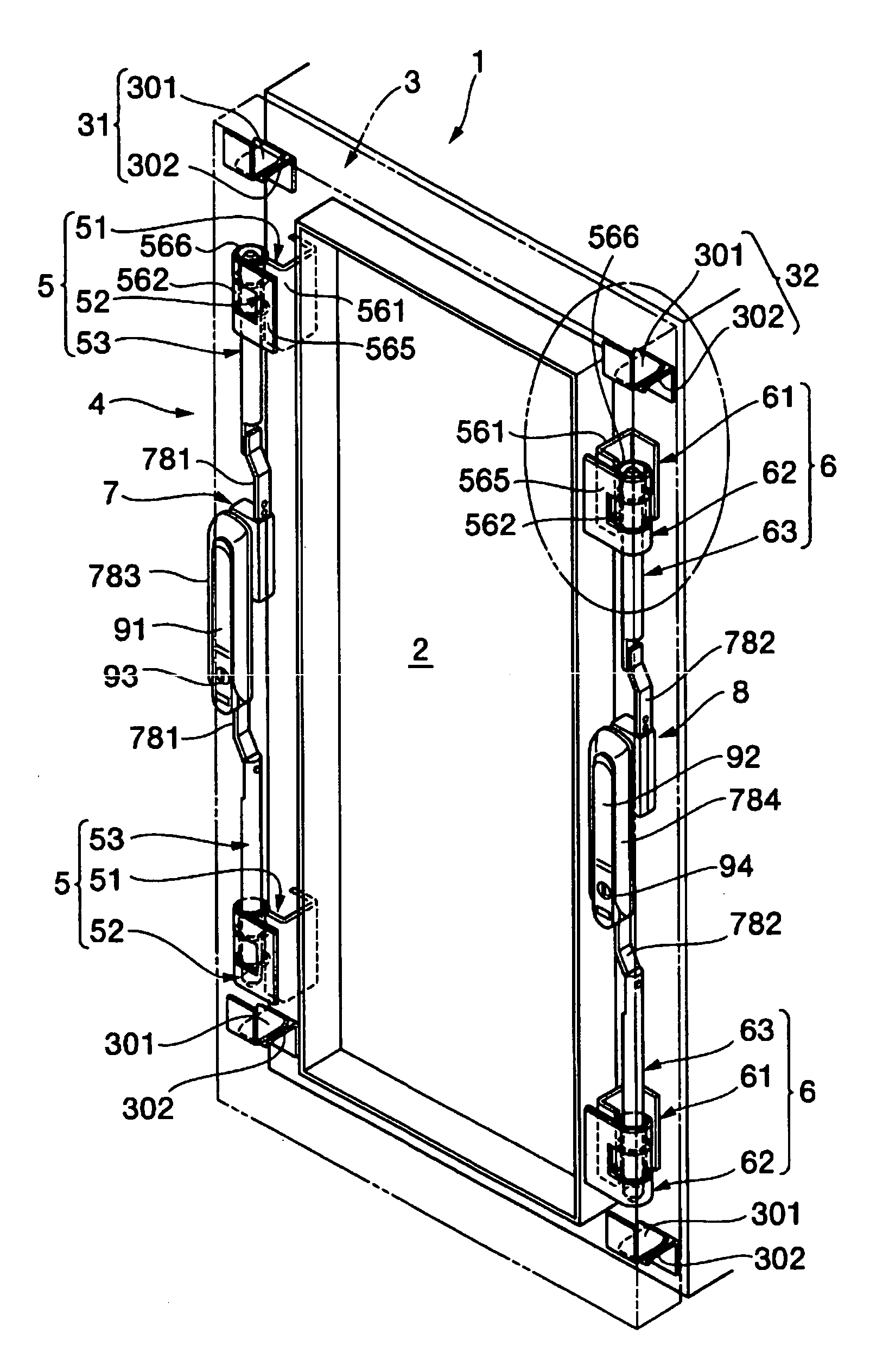
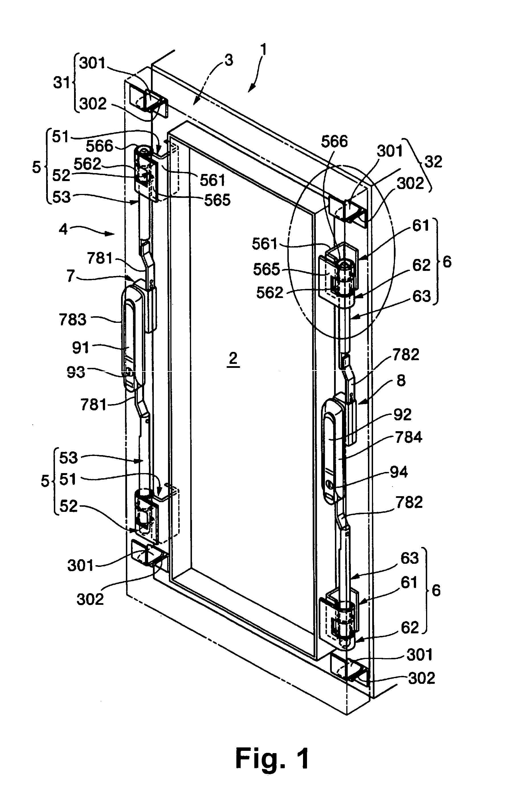
[0057]The best mode of the present invention will now be explained with reference to the attached drawings. Referring to FIG. 1, 1 refers to a cabinet body (casing), which is in the shape of a generally elongate box made of steel plates or the like, and has an opening 2 formed in its front face. The opening 2 is formed in a rectangular shape slightly smaller than the outline of the front face of the cabinet body 1, and is projected forward from the front wall of the cabinet body 1 in a frame form. 3 refers to a door for opening / closing the opening 2 of the cabinet body 1. The door 3 is made of a steel plate or the like material, and includes a principal face wall having the same shape and size as the outline of the front face of the cabinet body 1, and circumferential walls bent along and formed continuously from the edges of the principal face wall. The door 3 is in a thin box shape open on the inner face. 4 refers to a dual-opening mechanism of a door, which is adapted to open / clo...


PUM


Abstract

A door can be opened from either direction, from the left or the right. A double direction opening mechanism for a door has a first and second hinge pairs (5, 6), a first and a second hinge pin drive mechanism (7, 8), and a first and a second handle (91, 92). When either the first or the second handle (91, 92) is selectively operated, either the first or the second hinge pin pair (53, 63) is drawn out from either the first or the second hinge pair (5, 6). Then, a door (3) is rotated for opening / closing about either or the hinge pin pairs (53, 63) joined to the other of the first or the second hinge pair (5, 6).

Description

FIELD OF ART[0001]The present invention relates to a dual-opening mechanism of a door for use in a cabinet for a distribution board, a server rack, or the like.BACKGROUND ART[0002]A conventional door of a cabinet for a distribution board or the like is mounted to a cabinet body for opening / closing motion by means of hinges fixed in either right or left side Of the door, and is equipped with a lock device fixed in the opposite side of the door. Such a lock device is composed of a shaft rotationally operated with a handle, a lever and a latch rotating with the shaft, a pair of rods moving up and down in response to the motion of the lever, an engagement roller attached to an end of the rod, and the like elements. The latch and the engagement roller engage the inner periphery of the opening of the cabinet body to prevent opening operation of the door. When the shaft-is rotated by operating the handle, the latch and the engagement roller move back and are released from the engagement wi...

Claims


Application Information

Patent Timeline
Patent Type & Authority Patents(United States)
IPC IPC(8): E05D15/50E05B63/14E05C9/04F16C11/04F16C11/10H02B1/30H02B1/38H05K5/03H05K7/18
CPCE05D15/502H02B1/38Y10T16/527E05Y2900/208
Inventor YAMADA, AKIFUMI
Owner TAKIGEN MFG CO LTD
Why Eureka
Try Eureka