Tool with motion and orientation indicators

Active Publication Date: 2007-02-27
SZIEFF WILLIAM
View PDF16 Cites 107 Cited by
  • Summary
  • Abstract
  • Description
  • Claims
  • Application Information

AI Technical Summary

Problems solved by technology

While some bubble levels are mounted to hand drills via rotatable arms, such arms typically rotate in only a single plane and thus cannot be adjusted to monitor drill bit orientations in all possible starting orientati

Method used


Image

  • Tool with motion and orientation indicators
  • Tool with motion and orientation indicators
  • Tool with motion and orientation indicators

Examples


Embodiment Construction

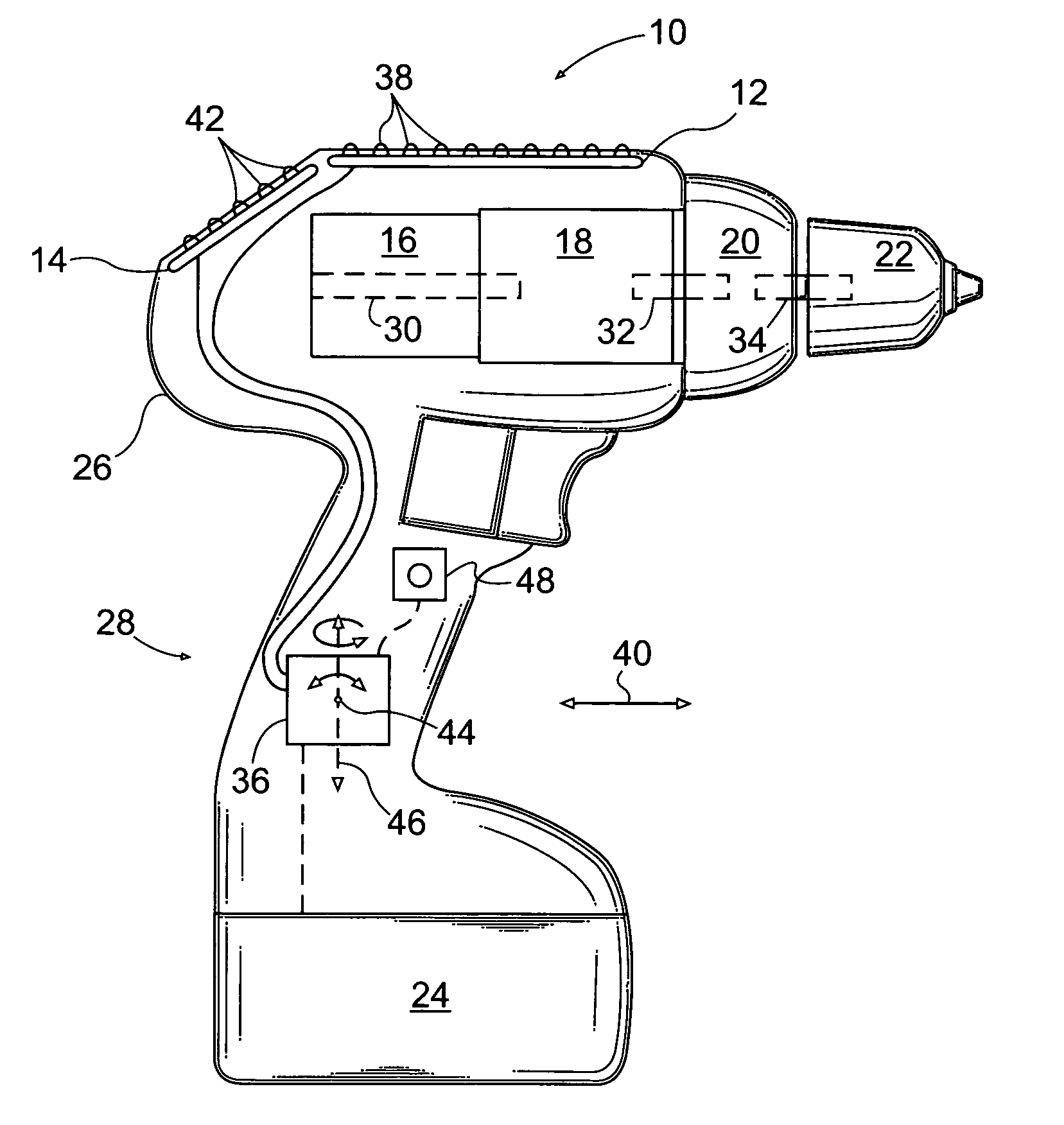
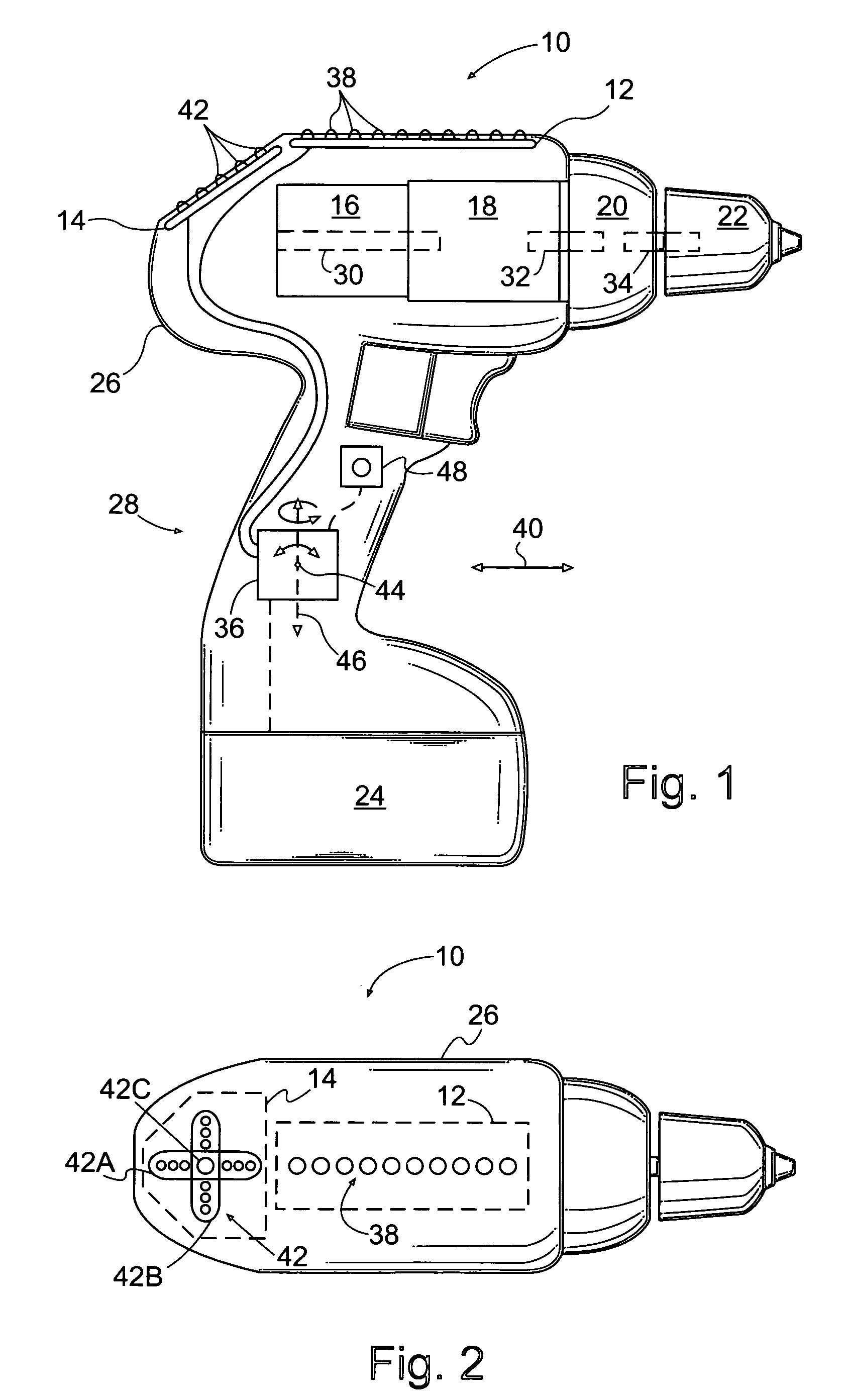
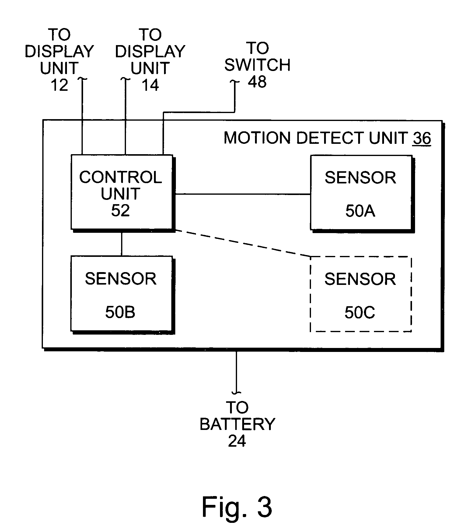
[0019]FIG. 1 is a side elevation view of one embodiment of a tool 10, wherein the tool is a portable power tool, namely a cordless hand drill. The tool 10 includes a motion detection unit 36 operably coupled to a housing 26 and a display unit. In the present embodiment, the display unit includes a first display unit 12 forming a depth indicator and a second display unit 14 forming a orientation indicator.

[0020]In the embodiment of FIG. 1 the hand drill 10 includes an electric motor 16 coupled to a chuck 22 via a transmission 18 and a clutch 20. A removable battery 24 provides electrical power for the hand drill 10. The electric motor 16, the transmission 18, and a portion of the clutch 20 are housed in the housing 26, and the removable battery 24 forms a lower extension of the housing 26. The housing 26 includes a handle portion 28 adapted for gripping by a human hand. The chuck 22 is adapted to grip a shaft of an accessory (e.g., a shaft of a rotary tool such as a drill bit).

[0021]...


PUM

PropertyMeasurementUnit
Depthaaaaaaaaaa
Responsivityaaaaaaaaaa
Levelaaaaaaaaaa

Abstract

A tool has a housing; a display unit attached to the housing; and a motion detection unit operably coupled to the housing and to the display unit, wherein the motion detection unit is configured to detect linear and rotational motion of the housing, to generate a first display signal indicative of the linear motion of the housing and to provide the first display signal to the display unit, and to generate a second display signal indicative of the rotational motion of the housing and to provide the second display signal to the display unit.

Description

CROSS-REFERENCE TO RELATED APPLICATIONS[0001]This application for a utility patent is a continuation-in-part of a previously filed utility patent, still pending, having the application Ser. No. 10 / 916,163, filed Aug. 11, 2004.STATEMENT REGARDING FEDERALLY SPONSORED RESEARCH[0002]Not ApplicableBACKGROUND OF THE INVENTION[0003]1. Field of the Invention[0004]This invention relates generally to tools, and more particularly to a tools that includes a movement indicator and a orientation indicator for indicating the position and orientation of the tool with respect to a reference location.[0005]2. Description of Related Art[0006]A hand drill is a common type of portable power tool. When drilling a hole with a hand drill it is often desirable to maintain a particular orientation of a drill bit with respect to a material being drilled. It is often also desirable to know a depth of the drill bit into the material being drilled.[0007]Devices used with hand drills to monitor orientations of dr...

Claims


Application Information

Patent Timeline
IPC IPC(8): B23B45/14
CPCB25B21/00B25B23/00B25H1/0078B25F5/02Y10T408/21
Inventor SZIEFF, WILLIAM
Owner SZIEFF WILLIAM
Why Eureka
Try Eureka