Free spinning rim for motorcycles

a free spinning, motorcycle technology, applied in the direction of wheel protection, vehicle components, transportation and packaging, etc., can solve the problems of affecting the angular rotation of the spinning rim may be slowed, and the spinner mount would interfere with the axle shaft required for attaching a motorcycle or bicycle wheel to the vehicle frame, etc., to achieve the effect of increasing the spinning angular speed and reducing the angular rotation of the spinning

Inactive Publication Date: 2007-02-27
RIVERS JR MICHAEL +1
View PDF16 Cites 5 Cited by
  • Summary
  • Abstract
  • Description
  • Claims
  • Application Information

AI Technical Summary

Benefits of technology

[0016]A motorcycle wheel system is provided which enhances the aesthetic appeal of a motorcycle wheel when the motorcycle is stationary or in motion. The present invention is suitable for use with wheels including an axle shaft positioned through the wheel central axis of rotation for supporting the wheel's rotation. A suitable wheel for use with the invention is attachable to a vehicle frame on both sides of the wheel (via the axle shaft) permitting viewing of the wheel rotation by an outside observer positioned on either side of the wheel. The present invention enhances the aesthetic appeal of the wheel by providing a spinning rim attachable to either face of the wheel, which is rotatable at a different angular speed relative to the wheel.
[0017]In this way, the present invention provides a free rotating rim (“spinner” or “spinning rim”), which may simulate wheel rotation when the motorcycle is at a standstill, or may simulate a different angular speed of the wheel than is ordinarily required to move the vehicle at the perceived vehicle speed.
[0018]The spinner is placed in rotational propinquity to the vehicle wheel. When the motorcycle is in motion, the spinner may rotate at a different rotational speed than the speed of the motorcycle wheel and may continue to rotate relative to the motorcycle wheel when the wheel comes to a stop. The different rotational speed of the spinner relative to the wheel provides aesthetically pleasing advantages over the prior art. For example, if the rotational speed of the spinner is less relative to the rotational speed of the motorcycle wheel, then the vehicle may appear to an outside observer to be hovering. Further, should the spinner rotate at the same rotational speed or a greater rotational speed than the motorcycle wheel, then the motorcycle may appear to be stationary or moving at a fast or faster rate than the actual vehicle speed. Further still, other visually pleasant effects may be achieved where the spinner continues to spin for an extended period of time after the vehicle ceases motion.

Problems solved by technology

Consequently, the Fowlkes invention is not suitable for use on vehicles on which the wheels include a central axle shaft or hub traversing therethrough, for attachment to a vehicle frame at opposing ends of the axle.
As can be seen, since Fowlkes discloses a system including a spinner mount positioned centrally to the spinner assembly, the spinner mount would necessarily interfere with the axle shaft required for attaching a motorcycle or bicycle wheel to the vehicle frame.
In addition, the spinner mount and spinner assembly of Fowlkes, when take in combination as intended, or individually, is too bulky around the wheel axis of rotation for use with a motorcycle or bicycle wheel, since little room exists for attaching the Fowlkes spinner and spinning mount between the wheel and vehicle frame.
More particularly, since the Fowlkes spinner mount is central to the wheel, the spinner mount makes it impossible to traverse a shaft through the spinning mount for attachment to the motorcycle or bicycle frame as required by most motorcycle or bicycle wheels.
Consequently, the Fowlkes system is unsuitable for use with a motorcycle or bicycle wheel, or the like requiring attachment to the frame of both sides of the wheel via an axle shaft.
Additionally, the construction of the Fowlkes spinner assembly, which, as noted, interferes with the placement of a motorcycle or bicycle wheel axle shaft, is only suitable for use with vehicle wheels with only one face viewable to an outside observer during use.
Thus, as noted, the Fowlkes support frame interferes with the position of the axle shaft.
As such, the Fowlkes invention is also not suitable for use with a vehicle wheel wherein the rotation of the wheel is fully observable by an outside observer from either side.

Method used


Image

  • Free spinning rim for motorcycles
  • Free spinning rim for motorcycles
  • Free spinning rim for motorcycles

Examples


Embodiment Construction

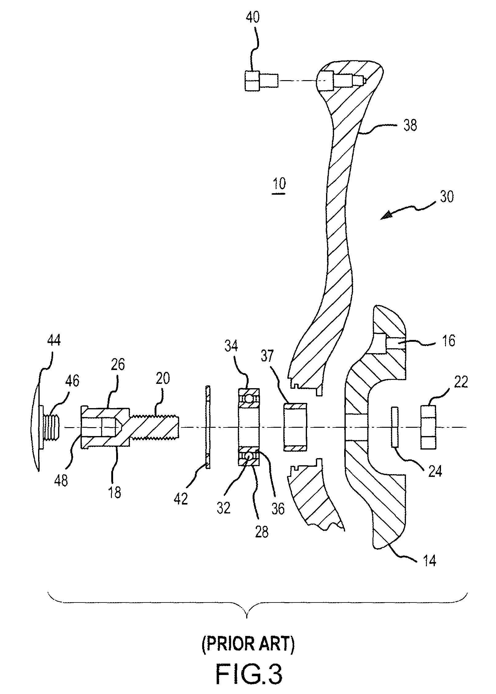
[0045]The present invention may be described herein in terms of functional components. It should be appreciated that such functional components may be realized by any number of hardware components configured to perform the specified functions. For example, the present invention may employ various friction-reducing components, e.g., ball bearing casings, spherical or cylindrical bearings, pneumatically sealed friction-reducing gel casings and the like, which may permit a first wheel component to rotate in proximity to a second wheel component, with little restriction of movement.

[0046]It should be appreciated that the particular implementations shown and described herein are merely exemplary and are not otherwise intended to limit the scope of the present invention. Indeed, for the sake of brevity, conventional friction-reducing principles and components for enabling motorcycle motion will not be discussed herein. Furthermore, the connecting lines shown in the various figures contain...


PUM


Abstract

A free spinning rim assembly is provided which is mountable to a first and second face of a motorcycle wheel including an axle shaft through its axis of rotation. The spinning rim assembly includes a spinner, which rotates about and is positioned circumspect the axle shaft, in proximity to the wheel face. The spinner rotates around the axle shaft at a different angular speed relative to the wheel on which it is mounted. The spinning rim assembly includes a spinning rim having a central bore, which is supported by a friction reducing means positioned in the spinner central bore. The friction reducing means is supported by a retaining means, which is further supported by the wheel hub.

Description

RELATED APPLICATIONS[0001]The present application relates to and claims priority to U.S. Provisional Application No. 60 / 416,103 entitled “Free Spinning Rim for Motorcycles,” filed Sep. 12, 2002, herein incorporated by reference in its entirety.FIELD OF INVENTION[0002]This invention relates generally to a wheel rim for motorcycles, and more particularly to a free spinning rim for use with wheels attached to a vehicle frame on both sides of the wheel face.BACKGROUND OF THE INVENTION[0003]In recent years, motorcycle manufactures have attempted to find ways to distinguish their products from their competitors. In doing so, the manufactures have focused on differing ornamental features and engine designs. The result is that the motorcycles on the market typically include different colors, shapes, and sizes of the motorcycle frame.[0004]In some instances, to distinguish their product, motorcycle manufactures have developed different ornamental designs directed toward the appearance of the...

Claims


Application Information

Patent Timeline
Patent Type & Authority Patents(United States)
IPC IPC(8): B60B7/20B60B7/04
CPCB60B7/20
Inventor RIVERS, JR., MICHAELMATHIS, MARC C.
Owner RIVERS JR MICHAEL
Why Eureka
Try Eureka