
Apparatus and method to detect an intrusion point along a security fence

a technology of intrusion detection and apparatus, applied in the field of apparatus and methods to detect intrusion points along security fences, can solve the problems of inability to accurately determine the length of the fence being monitored by the system, the inability to bypass the deterrent fence, and the inability to monitor the length of the fence. to achieve the effect of accurate determination and display

Inactive Publication Date: 2007-02-27
HUNEED TECH
View PDF24 Cites 20 Cited by
  • Summary
  • Abstract
  • Description
  • Claims
  • Application Information

AI Technical Summary

Benefits of technology

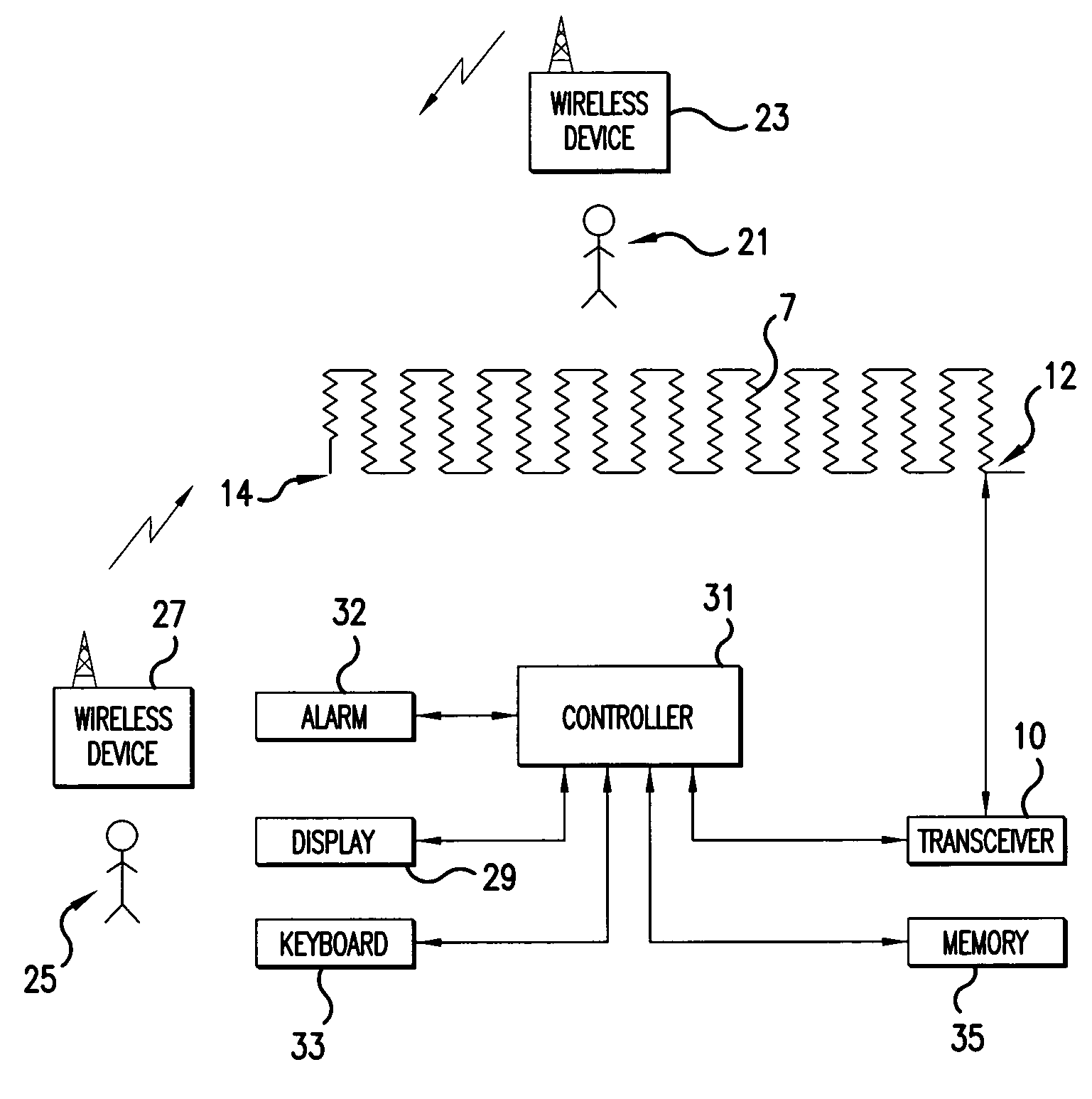
[0022]The present invention offers an improved system and method for locating a potential breach in a fiber optic cable enhanced, security fence. The present invention discloses an improved system and method, which allows security personal to more quickly appreciate a general location of a potential breach (PB) in the security fence, and to more accurately locate the PB for later inspection, service and repair.
[0024]These and other objects are accomplished by a system and method for establishing a look-up table to be used by a monitoring system for monitoring a security fence. The monitoring system evaluates the integrity of a fiber optic cable, having a weave pattern and attached to a security fence. Any breakage in, bending of, or stress on the fiber optic cable is noted by the monitoring system, and a length of cable between the monitoring system and the affected portion of the fiber optic cable is determined. The look-up table is indexed to determine a zone of potential breach. Further, an average weave density of the affected zone is computed, so that an approximate location of the potential breach within affected zone, in terms of ground distance, can be accurately determined and displayed.

Problems solved by technology

However, determined individuals, such as criminals and terrorists, may easily bypass deterrent fences by using common tools, such as wire or bolt cutters to simply make a passageway therethrough.
However, such conventional monitoring systems are far from foolproof, as humans and animals can be distracted and often do not monitor closely due to boredom.
However, it should be noted that the length of fence being monitored by the system is usually quite long.
In most circumstances, such a fence is too long to be monitored by a person or camera from a single vantage point.
First, it is difficult to locate points along a fence line based upon a known distance from a start point of the fence.
If the distance is long, it is tedious to measure such a distance, and the measurement is prone to error.
Further, obstacles along the fence line can further hinder a measurement from the start of the fence.
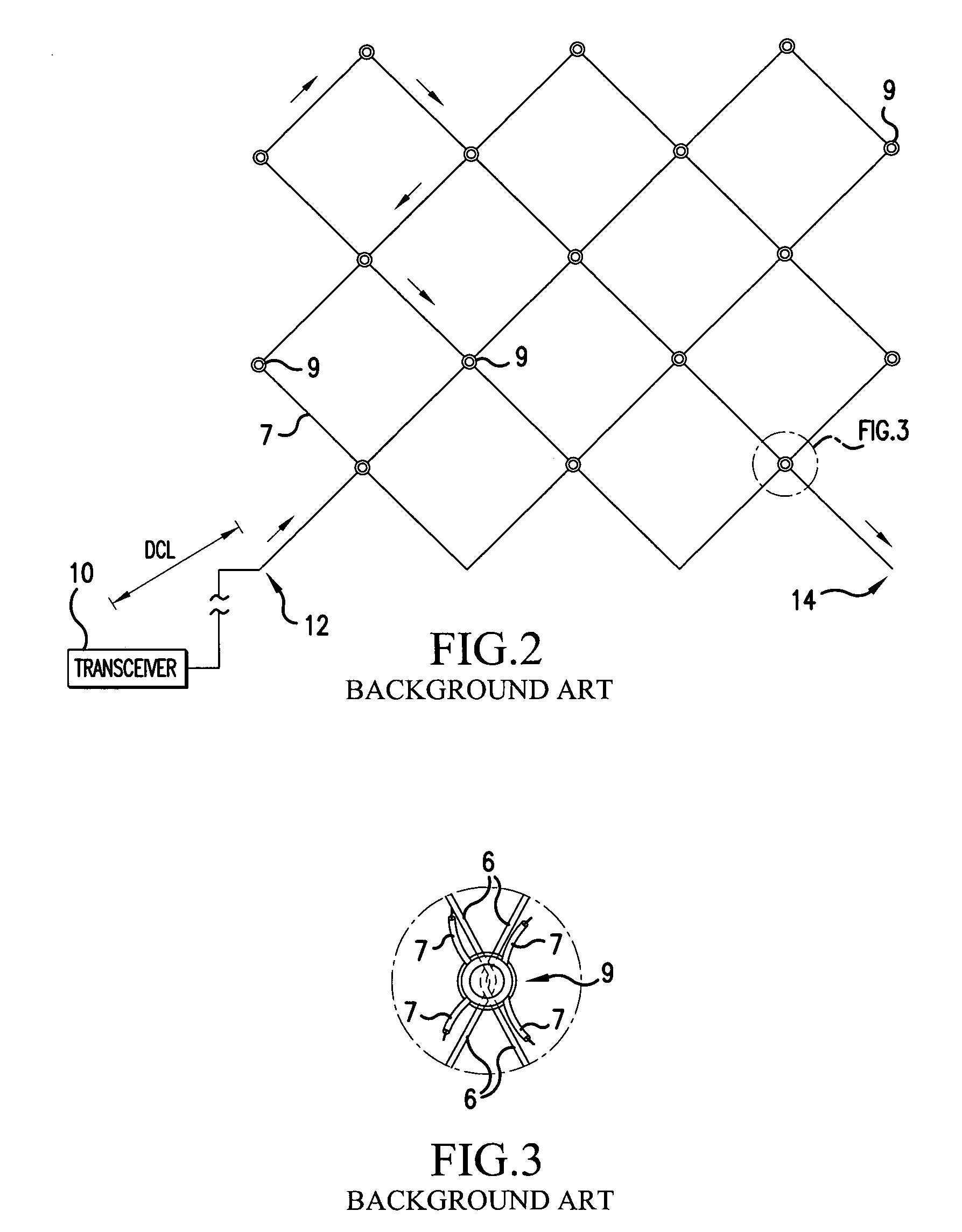
Second, the value CLM, which represents an average cable length used per meter of ground length, is a very troublesome value.
In reality, it is very difficult to maintain a relatively constant CLM along the entire length of the fence line.
Further, it is difficult, and hence time consuming and expensive, to maintain a constant weave density for the weave pattern of the fiber optic cable 3.

Method used


Image

  • Apparatus and method to detect an intrusion point along a security fence
  • Apparatus and method to detect an intrusion point along a security fence
  • Apparatus and method to detect an intrusion point along a security fence

Examples


Embodiment Construction

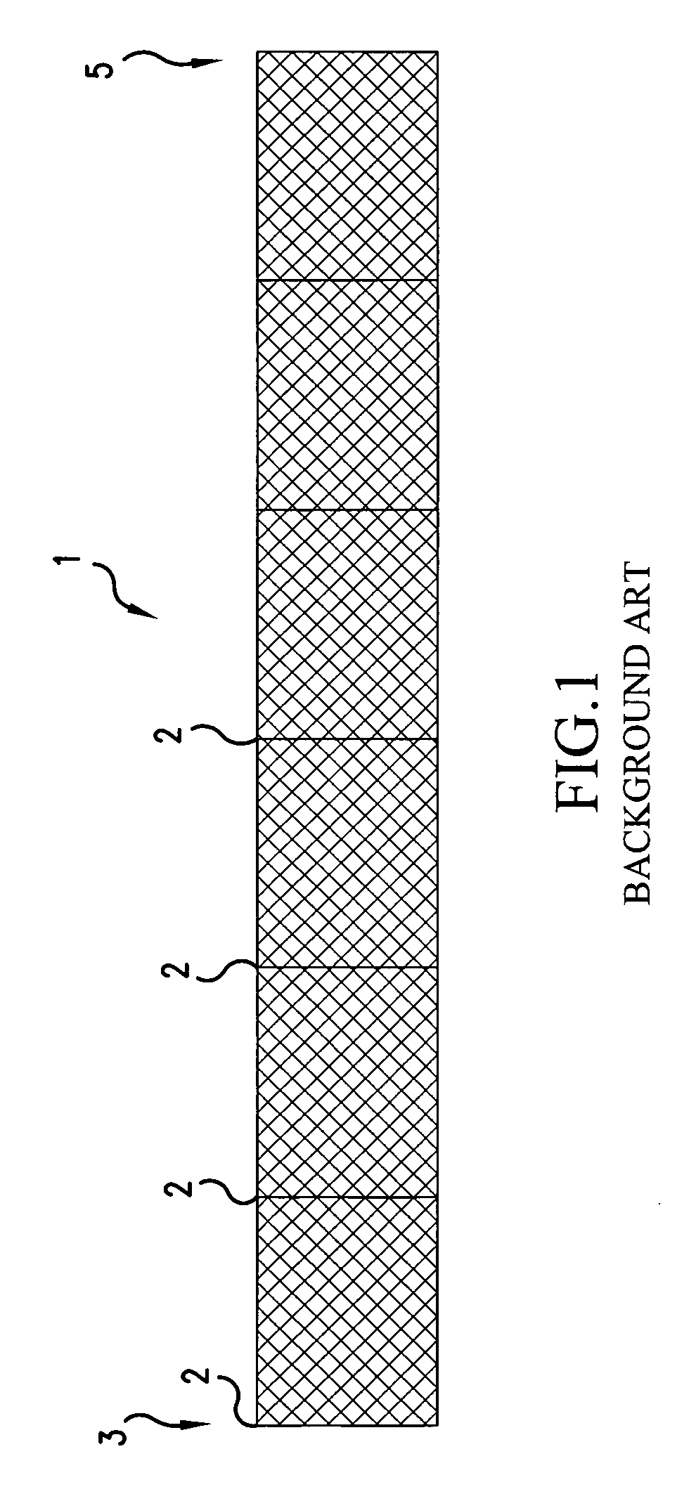
[0034]The present invention provides an improved system and method for more accurately detecting the location of a potential breach (PB) point in a fiber optic cable enhanced, security fence, such as the fence 1 illustrated in FIGS. 1–3. Reference will be made to FIGS. 4–7 to describe the system and method of the present invention.

[0035]As illustrated in FIG. 4, the security fence 1, in accordance with the present invention, is divided into a plurality of zones Z1, Z2, Z3, Z4, . . . Zn. Each zone can be defined between posts 2 of the security fence 1, or between installed signals, such as light signals 4, or between natural objects, such as trees, streams, or rocks 6. As illustrated in FIG. 4, Zone Z1 is 30 meters in length and extends between two posts 2 of the security fence 1. Of course, there would most likely be several posts 2 residing within zone Z1, but for clarity's sake only the start and end posts 2 are illustrated. Zone 2 is 50 meters in length and extends between a fenc...


PUM


Abstract

A monitoring system evaluates the integrity of a fiber optic cable, having a weave pattern and being attached to a security fence. To establish and calibrate the monitoring system, the present invention provides a system and method for establishing a look-up table to be stored in a memory. Any breakage in, bending of, or stress on the fiber optic cable is noted by the monitoring system by an alarm, and a length of cable between the monitoring system and the affected portion of the fiber optic cable is determined. The look-up table is indexed to determine a zone of potential breach. Further, an average weave density of the affected zone is computed, so that an approximate location of the potential breach within the affected zone, in terms of ground distance, can be accurately determined and displayed.

Description

BACKGROUND OF THE INVENTION[0001]1. Field of the Invention[0002]The present invention relates to a security fence of the type employing a fiber optic cable to detect intrusion or tampering. Further, the present invention relates to a method and apparatus for calibrating and initializing such a system, so that the system accurately approximates an intrusion or tampering location along the security fence.[0003]2. Discussion of the Related Art[0004]Security fences are widely used today. For example, security fences usually surround the perimeters of military facilities, some government agencies, airports, residences of celebrities and politicians, and other such areas. Simple fences are effective in alerting an innocent passerby that a certain area is restricted. Deterrent fences, such as fences with barbed wire, razor wire, or electrical currents therein, can also be effective at deterring less determined persons, such as children and vagabonds, from crossing into the restricted area....

Claims


Application Information

Patent Timeline
Patent Type & Authority Patents(United States)
IPC IPC(8): G01R13/00G01R29/26G08B13/186
CPCG08B13/186
Inventor CHUN, HONG GI
Owner HUNEED TECH
Learn More