Torque plate tool and method for sprinkler head installation

a technology of torque plate and sprinkler head, which is applied in the field of sprinkler head, can solve the problems of bulb being very strong, easily broken, and the bulb must be frangible for effective operation

Inactive Publication Date: 2007-03-06
VICTAULIC
View PDF26 Cites 25 Cited by
  • Summary
  • Abstract
  • Description
  • Claims
  • Application Information

AI Technical Summary

Problems solved by technology

The bulb is very strong in compression along its long axis but easily breaks when force is applied transverse to this axis.
However, the bulb must be frangible to operate effectively and is typically made of glass which is susceptible to damage.
Damage which can compromise the performance of the bulb may be caused during packing, shipping or installation of the sprinkler head and may comprise a scratch or nick in the bulb caused by a tool or another sprinkler head, as well as a crack or a small hole which allows the heat-sensitive fluid to escape.
If such damage is not prevented or at least mitigated, then it is possible that the bulb may fail prematurely at a temperature lower than the predetermined temperature, thus, triggering discharge from the sprinkler head in the absence of a fire condition.
This may result in extensive water damage to the building and its contents.
More seriously, the damage may prevent the sprinkler head from discharging at all, as may happen if the heat-sensitive fluid is permitted to leak out.
The problem is further complicated when recessed sprinkler heads are used, because for recessed installations, there is a greater likelihood of contamination of the sprinkler head since, being partially recessed, it is closer to the surfaces being finished.
While covers have been proposed to solve the aforementioned problems, some covers only protect the bulb from damage and leave the discharge orifice exposed to contaminants.
Other covers, which protect the entire sprinkler head, do not make any provisions for using tools to install the sprinkler heads.
Therefore, the installation procedure is cumbersome because the cover, initially installed over the sprinkler head for protection during shipping and handling, must be removed to allow the use of tools (typically a wrench to apply torque to a threaded nipple) for installation of the sprinkler head into the piping network.
Removal of the cover to provide access for tools leaves the bulb vulnerable during installation.
This is often not done, the covers being lost or deliberately discarded.

Method used


Image

  • Torque plate tool and method for sprinkler head installation
  • Torque plate tool and method for sprinkler head installation
  • Torque plate tool and method for sprinkler head installation

Examples


Embodiment Construction

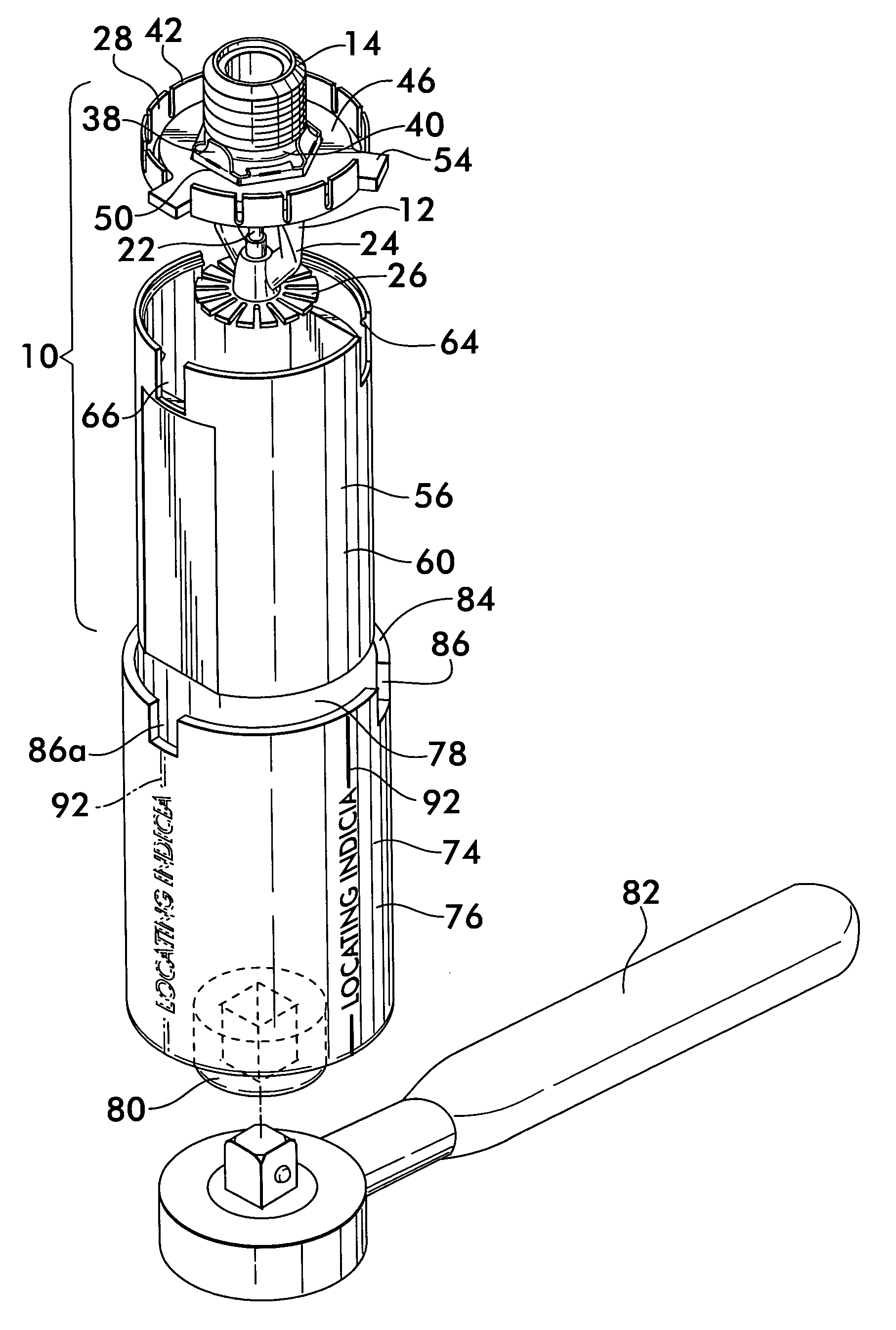
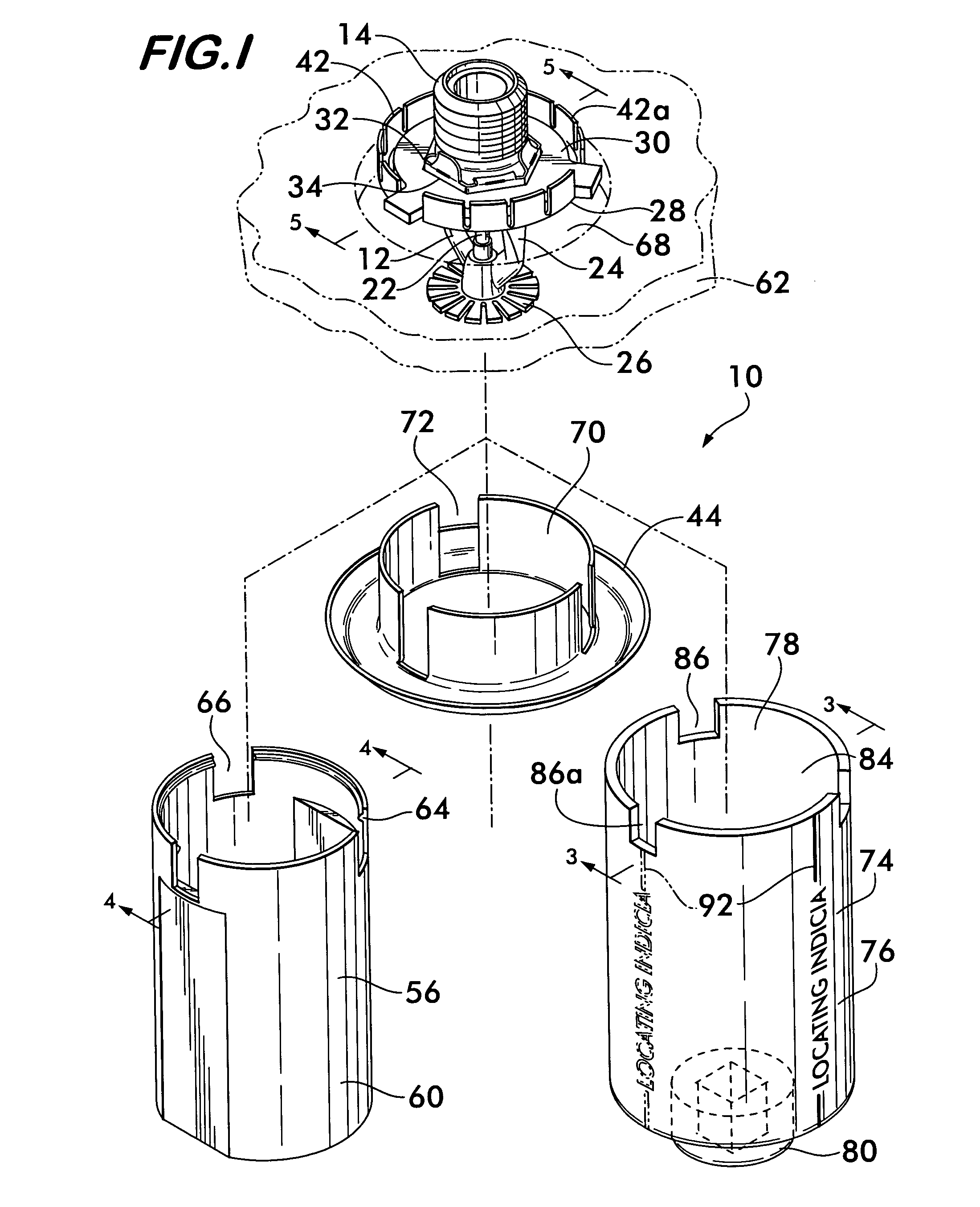
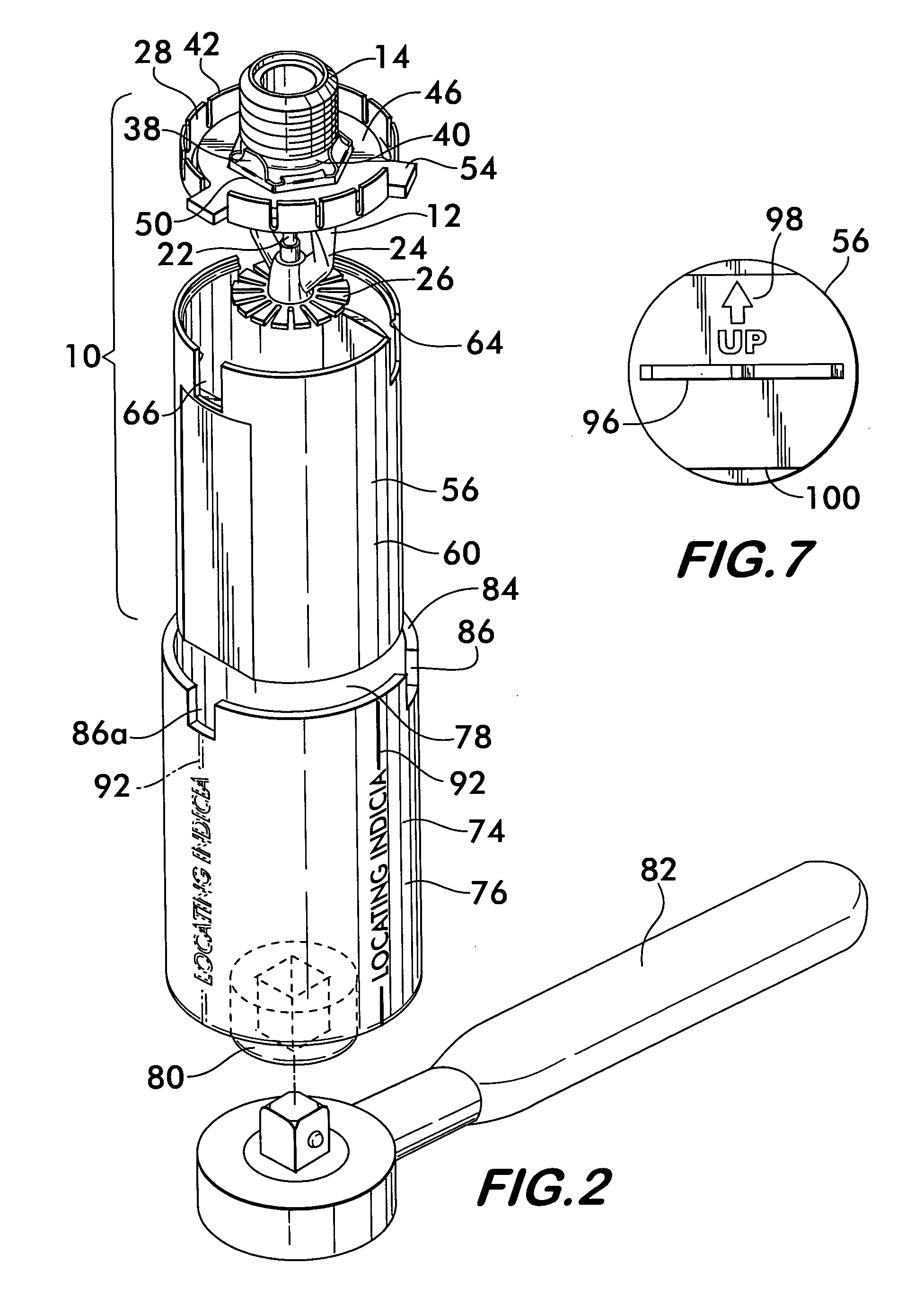
[0032]FIG. 1 illustrates the components of the sprinkler head assembly 10 according to the invention. Assembly 10 includes a sprinkler head 12 having a threaded nipple 14 for installing the head into a fitting of a piping network 16, partially shown in FIG. 3. Nipple 14 extends from a valve 18 having a discharge orifice 20 (see FIG. 6). With reference again to FIG. 3, valve 18 is normally biased into an open configuration but is held closed by a frangible glass bulb 22. As best shown in FIG. 1, bulb 22 is supported by two opposed arms 24 that extend from the valve 18 and also support a deflector plate 26. The bulb is held under compression by the valve biasing force, thereby keeping the valve 18 closed. Heat sensitive liquid within bulb 22 expands and causes the bulb to fracture when the ambient temperature surrounding the bulb reaches a predetermined elevated value indicative of a fire condition. When the bulb fractures, it allows the valve to open and discharge water through the d...


PUM


Abstract

A tool and a method for installing a sprinkler head in a threaded fitting of a fire suppression system is disclosed. The sprinkler head is protected by a cover. The tool is formed from an elongated body having a cavity that is sized to receive the cover. One end of the body interfaces with a wrench, the other end has one or more axially extending slots sized to receive the fingers of a torque plate affixed to the sprinkler head. The sprinkler head has a threaded nipple that engages the threaded fitting. The nipple is engaged with the fitting and torque is applied to it by engaging the slots of the tool with the fingers and turning the tool with the wrench. The tool has an external index allowing the sprinkler head to be angularly oriented to direct its discharge stream.

Description

FIELD OF THE INVENTION[0001]The invention relates to sprinkler heads used for fire suppression and to a tool and a method for installing sprinkler heads in a piping network.BACKGROUND OF THE INVENTION[0002]Fire suppression systems are used extensively in office buildings, warehouses, factories, hotels, homes and other buildings and structures to provide a reliable and effective means to suppress the spread of fire throughout the building or structure. Such systems may comprise a piping network extending throughout the building. The piping network is connected to a source of fire suppressing fluid, for example, water, and is in fluid communication with sprinkler heads distributed throughout the building which will discharge the fire suppressing fluid in the event of a fire.[0003]Each sprinkler head has a discharge orifice with a valve that is biased into a normally open position, but is held in a closed position against the biasing force by a frangible glass bulb that contains a heat...

Claims


Application Information

Patent Timeline
Patent Type & Authority Patents(United States)
IPC IPC(8): B25B13/48
CPCB25B13/50B25B13/06
Inventor IDE, STEPHEN R.
Owner VICTAULIC
Why Eureka
Try Eureka