
Methods of fabricating integrated circuit devices having fuse structures including buffer layers

a technology of integrated circuit devices and fuse structures, which is applied in the direction of semiconductor devices, semiconductor/solid-state device details, electrical apparatus, etc., can solve the problems of reducing the overall productivity of the process, requiring additional processing time, and unable to form an opening exposing the fuse pattern in the fuse region

Inactive Publication Date: 2007-03-06
SAMSUNG ELECTRONICS CO LTD
View PDF18 Cites 10 Cited by
  • Summary
  • Abstract
  • Description
  • Claims
  • Application Information

AI Technical Summary

Benefits of technology

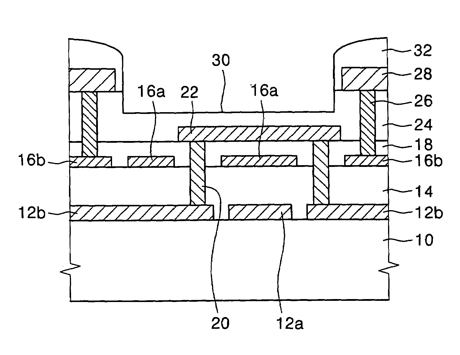
[0013]In some embodiments of the present invention, the integrated circuit device may further include a metal wiring and the metal wiring may be more remote from the integrated circuit substrate than the window layer. In certain embodiments of the present invention, the buffer pattern may include a first buffer pattern. The device may further include a first insulation layer between the first buffer pattern and the fuse pattern and a second buffer pattern between the first buffer pattern and the integrated circuit substrate. A second insulation layer may also be provided between the first and second buffer patterns.

Problems solved by technology

When a portion of the bit line is used as the fuse pattern it may be difficult to form an opening exposing the fuse pattern in the fuse region because the bit line is typically covered by multiple insulation layers, metal wirings and the like.
Accordingly, the opening exposing the fuse pattern may be deep and may require additional processing time due to the extra depth.
Thus, the overall productivity of the process may be reduced.
Furthermore, it may also be difficult to control a thickness of the window layer when the window layer is disposed in a deep opening.
When the upper electrode of the capacitor or the metal wiring is used as the fuse pattern, an underlying structure of the fuse pattern may be damaged by a laser beam used to cut the fuse pattern.
However, fabrication of the buffer layer plug may be complicated and time consuming.

Method used


Image

  • Methods of fabricating integrated circuit devices having fuse structures including buffer layers
  • Methods of fabricating integrated circuit devices having fuse structures including buffer layers
  • Methods of fabricating integrated circuit devices having fuse structures including buffer layers

Examples


Embodiment Construction

[0021]The present invention now will be described more fully hereinafter with reference to the accompanying drawings, in which preferred embodiments of the invention are shown. This invention may, however, be embodied in many different forms and should not be construed as limited to the embodiments set forth herein; rather, these embodiments are provided so that this disclosure will be thorough and complete, and will fully convey the scope of the invention to those skilled in the art. In the drawings, the thickness of layers and regions are exaggerated for clarity. It will be understood that when an element such as a layer, region or substrate is referred to as being “on” another element, it can be directly on the other element or intervening elements may also be present. It will be understood that when an element such as a layer, region or substrate is referred to as “under” or “beneath” another element, it can be directly under the other element or intervening elements may also be...


PUM


Abstract

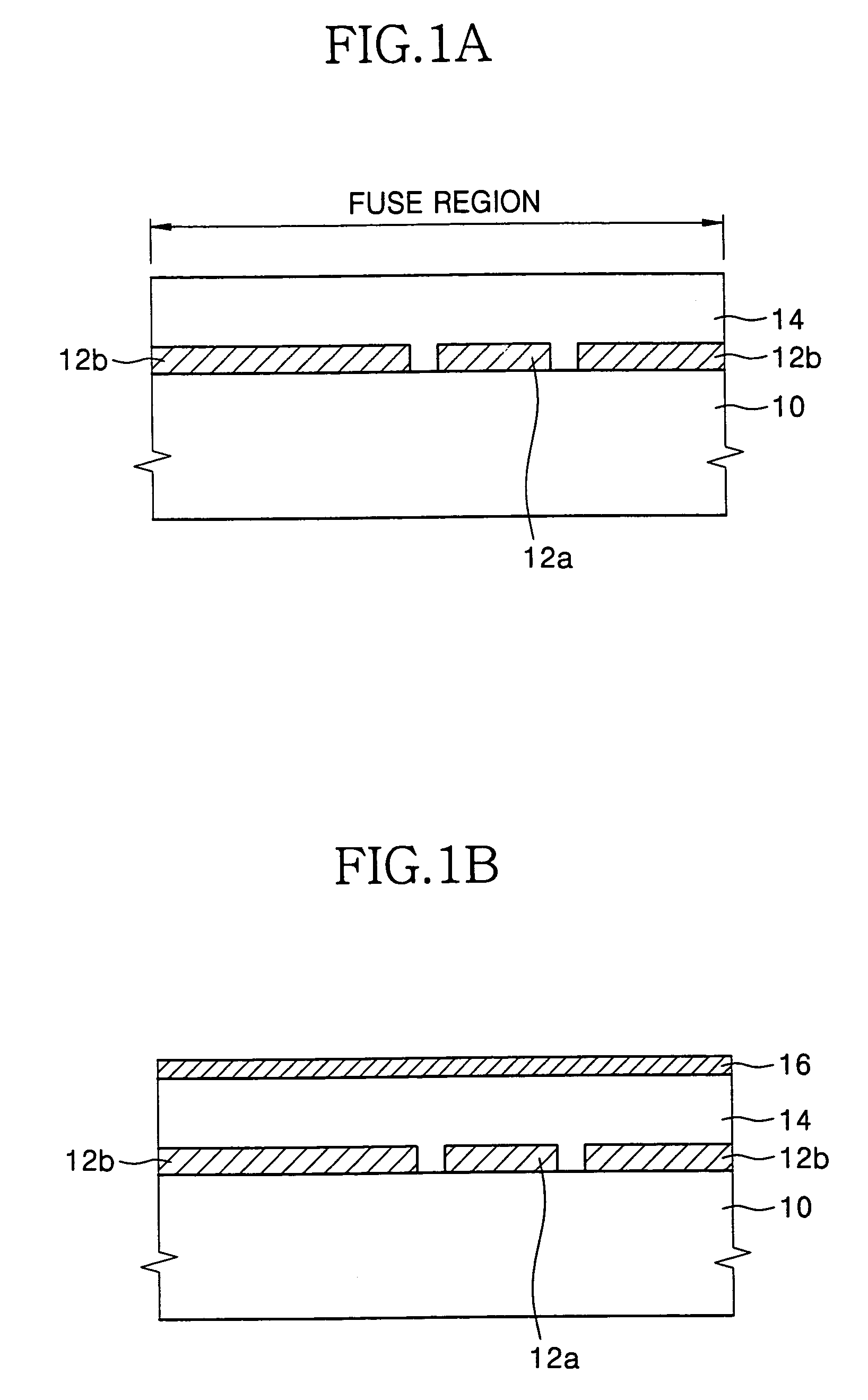
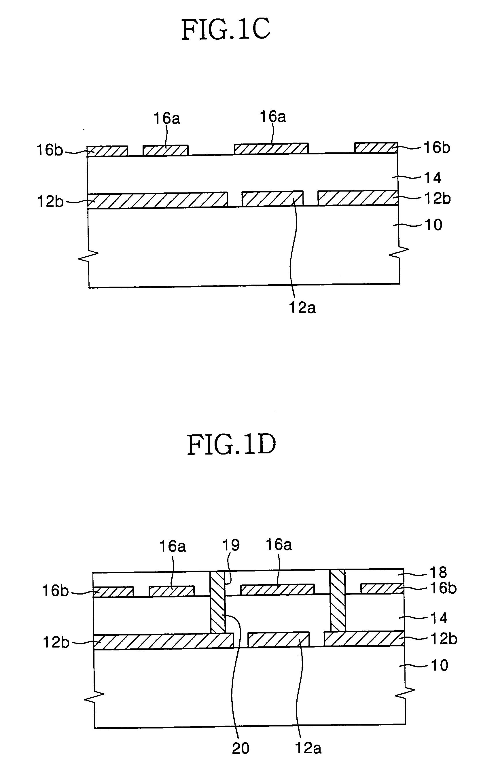
An integrated circuit device is provided including an integrated circuit substrate having a fuse region. A window layer is provided on the integrated circuit substrate that defines a fuse region. The window layer is positioned at an upper portion of the integrated circuit device and recessed beneath a surface of the integrated circuit device. A buffer pattern is provided between the integrated circuit substrate and the window layer and a fuse pattern is provided between the buffer pattern and the window layer. Methods of forming integrated circuit devices are also described.

Description

RELATED APPLICATION[0001]This application is related to and claims priority from Korean Patent Application No. 2002-68933 filed on Nov. 7, 2002, the disclosure of which is hereby incorporated herein by reference as if set forth in its entirety.FIELD OF THE INVENTION[0002]The present invention relates to integrated circuit devices and methods of fabricating the same and, more particularly, to fuse structures of integrated circuit devices and methods of fabricating the same.BACKGROUND OF THE INVENTION[0003]Conventional methods of manufacturing integrated circuit devices include a fabrication (FAB) process, i.e., forming cells on a substrate that make up the integrated circuit device, and an assembly process, i.e., packaging the cells on the substrate into chips. Furthermore, an electrical die sorting (EDS) process may be performed between the fabrication process and the assembly process to test electrical properties of the cells formed on the substrate.[0004]In particular, the EDS pro...

Claims


Application Information

Patent Timeline
Patent Type & Authority Patents(United States)
IPC IPC(8): H01L21/44H01L23/52H01L21/3205H01L21/82H01L21/8242H01L23/525H01L27/108
CPCH01L23/5258H01L27/10817H01L27/10885H01L27/10888H01L27/10894H01L27/10897H01L2924/0002H01L2924/00H10B12/318H10B12/50H10B12/482H10B12/485H10B12/09H01L21/82
Inventor KIM, HYUN-CHUL
Owner SAMSUNG ELECTRONICS CO LTD
Learn More