
Flexible sleeve for connection to a plumbing fixture

a flexible sleeve and plumbing fixture technology, applied in the direction of pipe connection arrangements, water closets, pipes/joints/fittings, etc., can solve the problems of limited flexibility and depth connection distance, limited use of angled connections, awkward or inconvenient opening of toilet bowls

Inactive Publication Date: 2007-03-13
COFLEX SA DE CV
View PDF20 Cites 49 Cited by
  • Summary
  • Abstract
  • Description
  • Claims
  • Application Information

AI Technical Summary

Problems solved by technology

However, in making openings through floors and in making the connection between the toilet bowl discharge and the waste drainpipe, there is some likelihood that the toilet bowl opening will be in an awkward or inconvenient place.
A problem associated with the previously described apparatuses is that even though they provide some flexibility, both are comprised of rigid connecting conduits, and therefore provide limited flexibility and depth connection distances.
But the problem with the apparatus described in U.S. Pat. No. 6,052,839 is its minimum offset.
More specifically, because it has a connecting rigid conduit in the shape of an elbow, its use is limited to angled connections.
Because of the rigidity of the conduit portions of the closet flanges that are currently available, there are several problems related with offset, angled and uneven installations.
Those solutions are expensive and can cause delays in the installation process.

Method used


Image

  • Flexible sleeve for connection to a plumbing fixture
  • Flexible sleeve for connection to a plumbing fixture
  • Flexible sleeve for connection to a plumbing fixture

Examples


Embodiment Construction

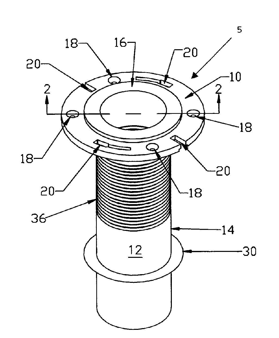
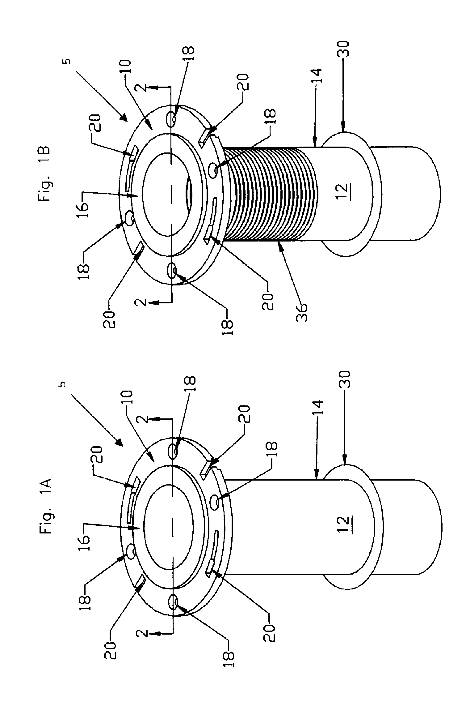
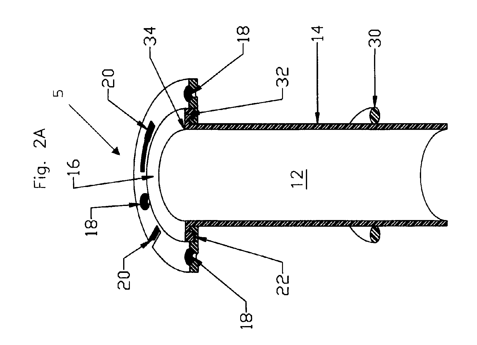
[0028]FIGS. 1A–2C depict several alternative embodiments of the improved flange. In particular, FIGS. 1A–1B depict schematic isometric perspective views of the improved flange. Cross-sectional views of the flanges depicted in FIGS. 1A–1B are also depicted in FIGS. 2A–2C. In each of these figures, the improved flange 5 comprises an outer flange 10 attached to a flexible sleeve 12 with an attaching lip 32, which is part of the upper portion of the sleeve 16. The attaching lip 32 is seated in the radial groove 22 and forms a seal between the attaching lip 32 and the outer flange 10. In addition, the flexible sleeve 12 has an O-ring type seal 30 that is mounted around the flexible conduit portion 14. The O-ring seal 30 can comprise a plurality of O-rings, such as ten O-rings, one to four O-rings, or only one O-ring.

[0029]As clearly shown in FIGS. 1A, 2B, and 3, the outer flange 10 is substantially cylindrical in shape, having a linear longitudinal axis 19 (shown explicitly in FIG. 3) ex...


PUM

PropertyMeasurementUnit
vertical distanceaaaaaaaaaa
diametersaaaaaaaaaa
diametersaaaaaaaaaa

Abstract

An improved water closet flange for connection to a plumbing fixture is described. The improved flange comprises an anchoring element or outer flange, connected to a flexible conduit tube or flexible sleeve, in which is attached an O-ring type of gasket. The improved flange connects a toilet bowl outlet to a waste drainpipe outlet without any flow reduction in between both connecting elements. The improved flange allows the connection between a toilet bowl discharge and a well placed vertical waste drainpipe. The improved flange also allows the connection between a toilet bowl discharge and a waste drainpipe outlet that is offset, horizontally oriented, or diagonally placed. The improved flange may further comprise an O-ring type of gasket disposed on the exterior of the flexible sleeve to provide a tight seal between the outer surface of the flexible sleeve and the inner surface of a waste drainpipe. The flexible sleeve can be implemented in a variety of sizes or diameters, including, for example, 3 inch (7.5 cm) and 4 inch (10 cm) diameters. An alternative embodiment of the flexible sleeve can fit either 3 inch or 4 inch drainpipes with the help of an appropriate O-ring seal of the appropriate dimensions.

Description

CROSS-REFERENCE TO RELATED APPLICATIONS[0001]This application is a divisional of U.S. application Ser. No. 10 / 370,747 filed Feb. 20, 2003, entitled “Improved Flexible Sleeve for Connection to a Plumbing Fixture,” which is incorporated by reference herein in its entirety for all purposes.FIELD OF THE INVENTION[0002]This application relates generally to devices for connecting plumbing fixtures to waste drain conduits, and more particularly to the combination of a specially configured flexible sleeve and a closet flange, which mounts a water closet (toilet) on a supporting floor surface and also provides a tight sealed interconnection between the water closet (toilet) and the water waste drain pipe, allowing a good connection even between uneven outlets.BACKGROUND[0003]Water closets, also called toilets, are waste disposal devices commonly installed in most bathrooms. These kinds of plumbing appliances generally have a water storing receptacle called a water tank that is attached to a ...

Claims


Application Information

Patent Timeline
Patent Type & Authority Patents(United States)
IPC IPC(8): E03D11/16F16L47/26
CPCE03D11/16F16L47/265F16L47/26
Inventor ORTIZ, EVODIOSADA, JORGETRUJILLO, ARMADOCORONADO, EDUARDO
Owner COFLEX SA DE CV
Learn More