Control for a bathtub waste water drain

Inactive Publication Date: 2008-02-28
WCM IND INC
View PDF7 Cites 32 Cited by
  • Summary
  • Abstract
  • Description
  • Claims
  • Application Information

AI Technical Summary

Benefits of technology

[0010]An overflow cap is mounted adjacent the first port. An elongated linkage connects the valve element to a motor system on the upper end of the drain pipe so that the movement of the motor stem in one d

Problems solved by technology

While such drain closures work well, they are not greatly convenient by reason of their being located on the bottom of the tub where the drain is located.
However, these are not easily adapted to the bathtub environment, and pose at least some

Method used


Image

  • Control for a bathtub waste water drain
  • Control for a bathtub waste water drain
  • Control for a bathtub waste water drain

Examples


Embodiment Construction

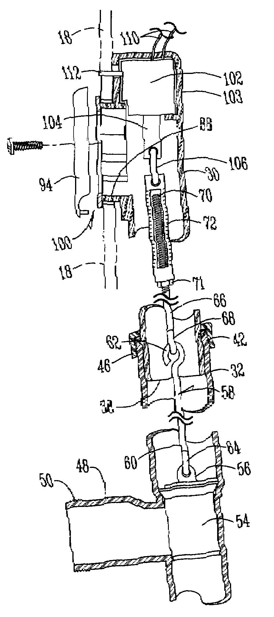
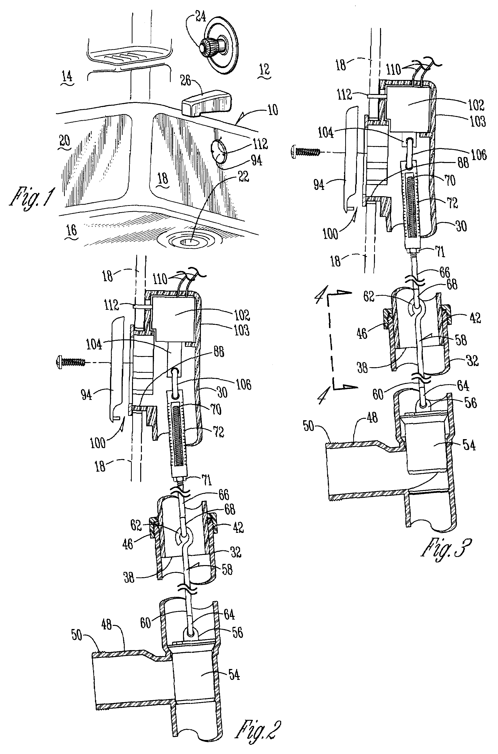
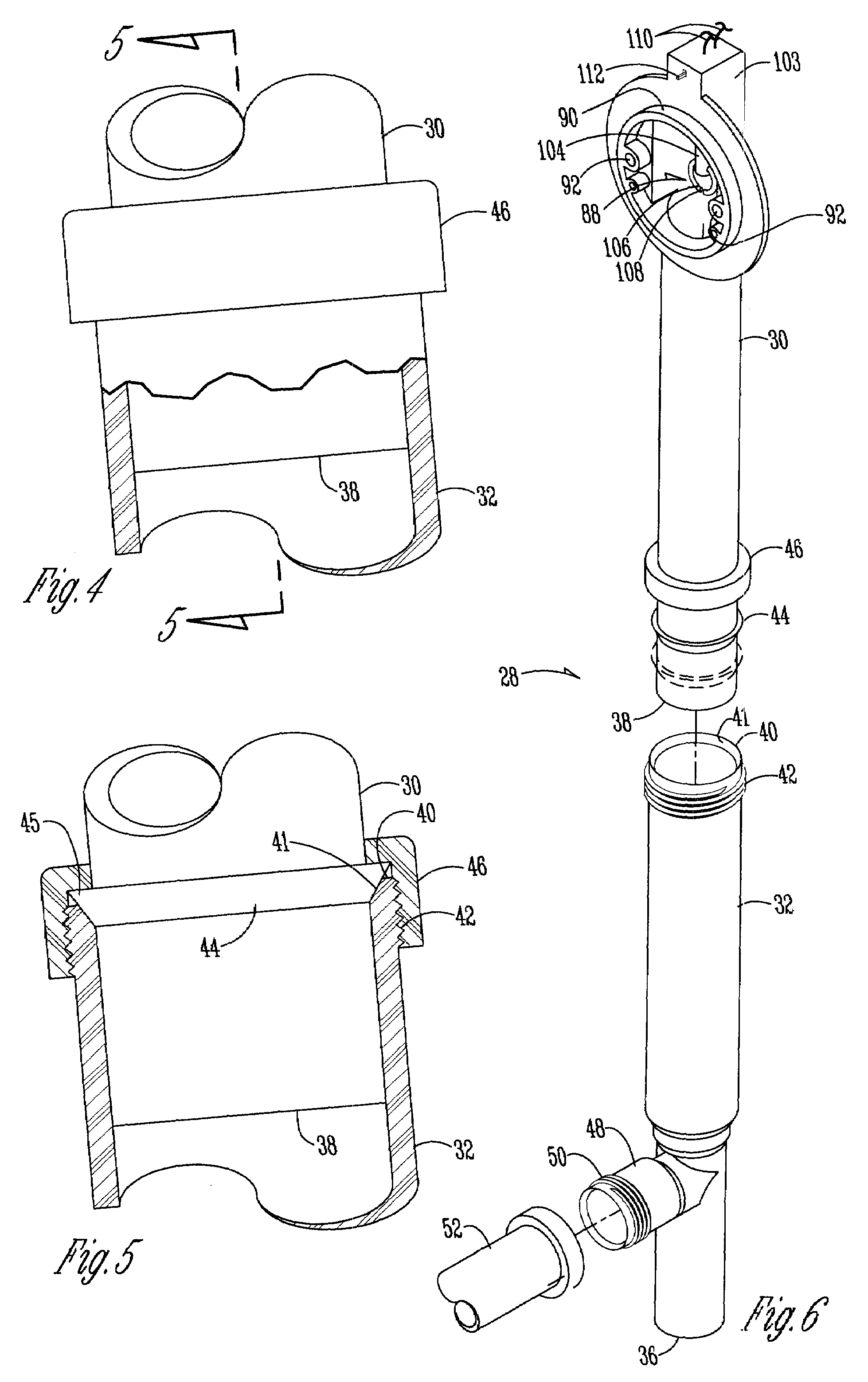
[0020]A bathtub (“tub”) 10 is mounted adjacent bathroom end wall 12 and sidewall 14, and has a bottom 16, top end wall 18, and top sidewall 20. A conventional tub waste water drain outlet 22 is located in bottom 16. A conventional water control valve 24 and water outlet 26 are mounted on the end wall 12. With reference to FIG. 6, a vertical drain pipe 28 has an upper portion 30 and a lower portion 32, and an upper end 34 and a lower end 36. The lower end 38 of the upper portion 30 is insertable in the upper end 40 of the lower portion 32. It should be noted that the upper end 40 is tapered around its inner edge 41. Exterior threads 42 extend around the upper end 40.

[0021]A tapered plastic seal ring 44 is slidably mounted on upper portion 30 and has a tapered lower edge 45 which is compatible with the tapered inner edge 41 of the lower portion 32. A lock connector nut 46 is slidably mounted on upper portion 30. When the seal 44 is located in the desired position on upper portion 30, ...


PUM


Abstract

A control for a waste water drain in the bottom of a bathtub which has an overflow port above the drain in the end wall of the bathtub has a vertical drain pipe having upper and lower ends. A first fluid port is located at the upper end of the vertical drain pipe and a second fluid port is located below the first fluid port for connection to a bathtub waste water drain. A valve element is slidably mounted in the vertical drain pipe adjacent the second port and is movable between a lower position to close the second port to fluid flow, and an upper position which will open the second fluid port to fluid flow. An electrical motor system is mounted adjacent the first port. An elongated linkage connects the valve element to the motor so that the rotation of the motor will raise and lower the valve element. The vertical drain pipe is length-adjustable.

Description

BACKGROUND OF THE INVENTION[0001]Bathtub drains commonly have a closure element therein which can open or close the drain by being lifted manually upward to open the drain or drop to an initial seating position to close the drain. While such drain closures work well, they are not greatly convenient by reason of their being located on the bottom of the tub where the drain is located.[0002]Linkage systems do exist in at least lavatories or the like where the waste water drain is opened or closed through a linkage system wherein the operative mechanism is located above the bottom level of the basin. However, these are not easily adapted to the bathtub environment, and pose at least some problems in maintaining the cleanliness of the fixture around the exposed end of the linkage system where the closure is operated.[0003]Variations in tub dimensions and the like sometimes make the adaptation of linkage systems difficult to install.[0004]It is therefore a principal object of this inventi...

Claims


Application Information

Patent Timeline
IPC IPC(8): E03C1/232
CPCE03C1/232E03C1/2302
Inventor BALL, WILLIAM T.
Owner WCM IND INC
Why Eureka
Try Eureka