Debris trap for a drain

a technology for drains and debris, applied in the field of drains, can solve the problems of hair and other debris clogging, difficult and time-consuming removal, and difficult and disgusting cleaning tasks

Active Publication Date: 2012-03-01
MEYERS LAWRENCE G
View PDF9 Cites 34 Cited by
  • Summary
  • Abstract
  • Description
  • Claims
  • Application Information

AI Technical Summary

Benefits of technology

[0006]It has been recognized that it would be advantageous to develop a

Problems solved by technology

One challenge with floor drains and other drains is the potential for clogs of hair and other debris.
However, with many of these, removal can be difficult and time-c

Method used


Image

  • Debris trap for a drain
  • Debris trap for a drain
  • Debris trap for a drain

Examples


Embodiment Construction

[0022]Reference will now be made to exemplary embodiments illustrated in the drawings, and specific language will be used herein to describe the same. It will nevertheless be understood that no limitation of the scope of the invention is thereby intended. Alterations and further modifications of the inventive features illustrated herein, and additional applications of the principles of the inventions as illustrated herein, which would occur to one skilled in the relevant art and having possession of this disclosure, are to be considered within the scope of the invention.

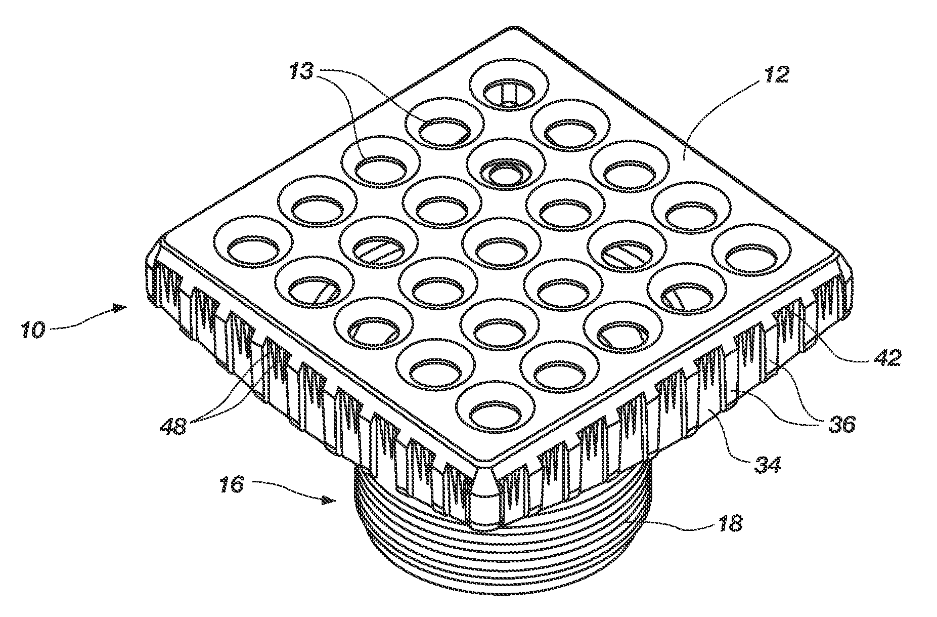
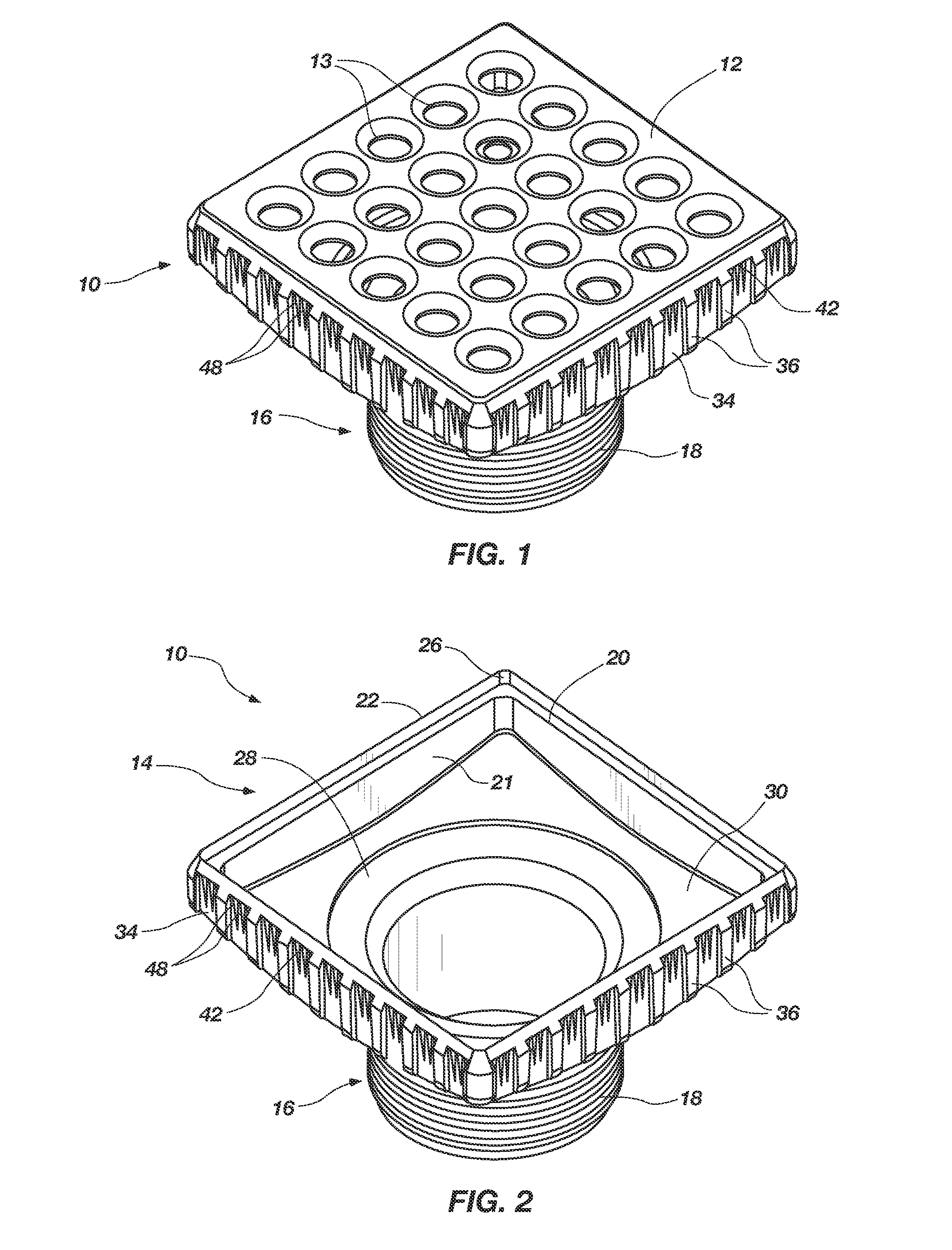
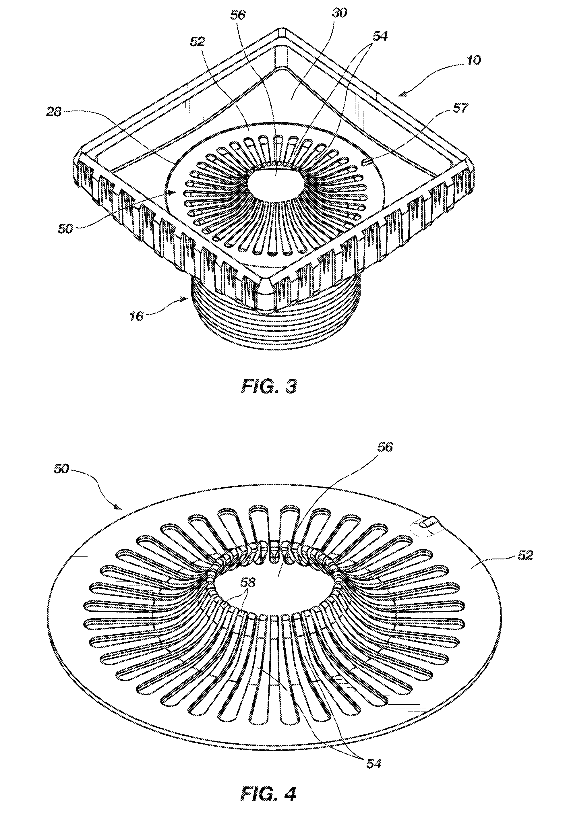
[0023]Shown in FIG. 1 is a drain body or riser 10 with a grate 12 having drain openings 13. The drain body is shown with the grate removed in FIG. 2. This drain body 10 is a one-piece unit, having a generally rectangular upper portion 14 defining an inlet, and a circular lower portion 16 defining an outlet and being configured to mate with an underdrain structure. It is to be understood that, while the drain body sho...


PUM

PropertyMeasurementUnit
Lengthaaaaaaaaaa
Radiusaaaaaaaaaa
Diameteraaaaaaaaaa

Abstract

A debris trap for a drain includes an annular rim, defining a center, with a plurality of radial prongs, extending from the rim toward the center, and oriented to catch debris in the drainage pathway. The debris trap is removably disposable within a drainage pathway of a drain body, below a removable drain grate thereof.

Description

BACKGROUND[0001]1. Field of the Invention[0002]The present disclosure relates generally to drains, such as for tiled showers and the like. More particularly, the present disclosure relates to a removable debris trap for a drain.[0003]2. Related Art[0004]There are a variety of styles and types of floor drains for showers and the like. Both round and square or rectangular drains are available, and there are a variety of mechanisms for connecting drain structures with associated drainage pipes. There are also a variety of materials and finishes that have been used for drains and drain grates. For many years, floor drains and grates have been made of non-corrosive metals, such as brass and stainless steel. More recently, because of their low cost and ease of use, polymer materials have been used for drain structures and drain grates, often in combination with metal structures. For example, drains comprising a polymer drain body and a metal drain grate are quite common. Drain grates comp...

Claims


Application Information

Patent Timeline
IPC IPC(8): E03C1/26B23P19/00
CPCE03C1/264Y10T29/49815E03F5/041B01D35/02B01D35/28E03C1/26E03F5/0408E03F5/06
Inventor MEYERS, LAWRENCE G.
Owner MEYERS LAWRENCE G
Why Eureka
Try Eureka