Adjustable mounting bracket

a mounting bracket and adjustable technology, applied in the direction of nuts, light support devices, building scaffolds, etc., can solve the problems of inability to provide adhesive attachment to the exposed substrate edge, attaching components designed for quick and easy connection, etc., and achieve the effect of quick and easy

Active Publication Date: 2007-03-20
PHYSICAL SYST
View PDF17 Cites 37 Cited by
  • Summary
  • Abstract
  • Description
  • Claims
  • Application Information

AI Technical Summary

Benefits of technology

[0006]In accordance with the invention, an improved attachment component comprising an adjustable mounting bracket is provided for secure and stable mounting as by adhesive attachment onto an exposed edge of a supporting substrate, wherein the mounting bracket is adapted for quick and easy subsequent mounting of a selected structure such as tubing, wire bundles, etc., relative to the substrate. The adjustable mounting bracket comprises a pair of slidably interfitting bracket members each having a generally L-shaped configuration to cooperatively define a slidably overlying pair of mounting plates and an associated pair of slidably separable clamp jaw plates. The slidably interfitting mounting plates accommodate adjustable spaced-apart separation of the clamp jaw plates to seat firmly against opposed surfaces of the exposed substrate edge, such as mounting onto a rib protruding from the substrate or mounting onto an inner diameter edge of an opening formed in the substrate.
[0009]In one alternative preferred form of the invention, the retainer initially supports the mounting plates of the adjustable bracket in relatively loosely connected relation to permit one of the mounting plates to be swingably or pivotally displaced relative to the other. In this embodiment, a first clamp jaw plate can be seated firmly against one surface of the exposed substrate edge, followed by pivoting movement of the other or second clamp jaw plate into firmly seated contact with an opposite surface of the substrate edge. The retainer incorporates a fastener which can then be tightened for securely interconnecting the overlying mounting plates, thereby securely clamping the clamp jaw plates onto the exposed substrate edge. Additional mounting ports and / or related fasteners may be provided on at least one of the mounting plates for facilitated subsequent connection of a selected structure or structures thereto.

Problems solved by technology

However, attachment components designed for adjustable quick and easy connection as by adhesive attachment to the exposed substrate edge have not been available, particularly with respect to accommodating a range of different edge wall thicknesses.

Method used


Image

  • Adjustable mounting bracket
  • Adjustable mounting bracket
  • Adjustable mounting bracket

Examples


Embodiment Construction

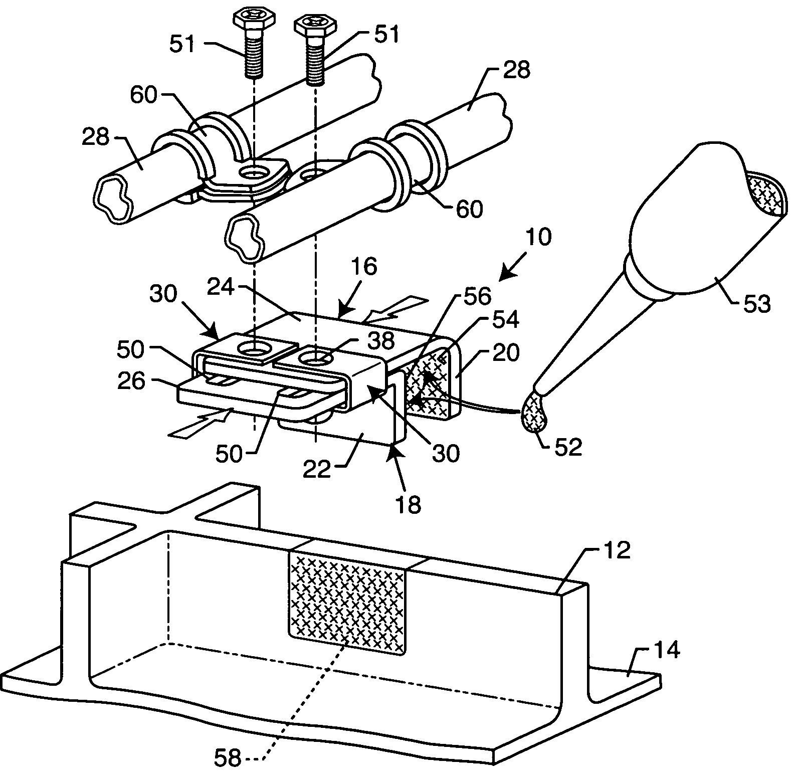
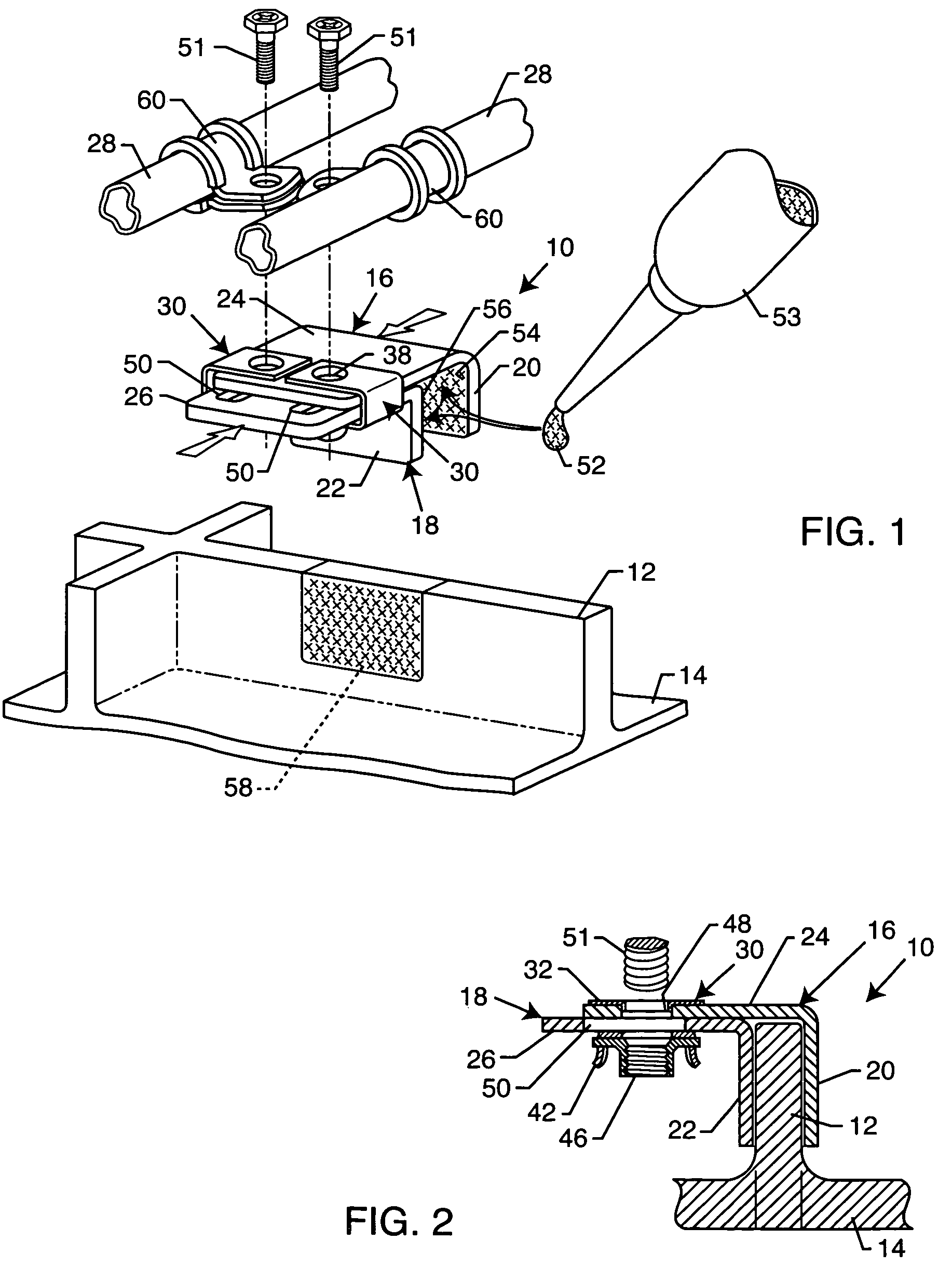
[0027]As shown in the exemplary drawings, an adjustable mounting bracket referred to generally in FIG. 1 by the reference numeral 10 is provided for quick and easy mounting as by adhesive connection onto an exposed edge 12 such as the illustrative standing rib formed on a substrate 14. The mounting bracket 10 includes a pair of adjustable bracket members 16 and 18 each having a generally L-shaped configuration and slidably nested one within the other to define a pair of clamp jaw plates 20 and 22 adapted for secure and stable adhesive attachment to opposed surfaces defined on the substrate rib or edge 12. The mounting bracket further includes a pair of slidably overlying mounting plates 24 and 26 adapted for convenient mounted support of one or more selected structures 28 such as lengths of tubing, wire bundles, or the like relative to the substrate 14.

[0028]FIGS. 1–2 depict the adjustable mounting bracket 10 of the present invention in accordance with one preferred form, for use in...


PUM


Abstract

An adjustable mounting bracket for secure mounting as by adhesive attachment onto an exposed edge of a substrate, wherein the mounting bracket is adapted for quick and easy subsequent mounting of a selected structure such as tubing, wire bundles, etc., relative to the substrate. The adjustable mounting bracket includes a pair of slidably interfitting, generally L-shaped bracket members which cooperatively define a slidably overlying pair of mounting plates and an associated pair of slidably separable clamp jaw plates. The slidably interfitting mounting plates accommodate adjustable spaced-apart separation of the clamp jaw plates to seat firmly against opposed surfaces of the substrate edge, such as mounting onto a rib protruding from the substrate or mounting onto an inner diameter edge of an opening formed in the substrate.

Description

[0001]This application claims the benefit of U.S. Provisional Application 60 / 581,902, filed Jun. 23, 2004.BACKGROUND OF THE INVENTION[0002]This invention relates generally to mounting brackets and fixtures adapted for connection as by adhesive attachment to a supporting substrate, wherein the mounting bracket is adapted for quick and easy subsequent mounting of a selected structure such as tubing, wire bundles, etc., relative to the substrate. More particularly, this invention relates to an adjustable mounting bracket designed for secure mounting onto an exposed edge of a substrate, such as mounting onto a rib protruding from the substrate or mounting onto an inner diameter edge of an opening formed in the substrate.[0003]Adhesive attachment assemblies or fixtures and related methods for securing an attachment component or element such as a patch, threaded screw, or other structure onto a supporting surface or substrate are generally known in the art. For example, it may necessary t...

Claims


Application Information

Patent Timeline
Patent Type & Authority Patents(United States)
IPC IPC(8): F16B1/00A47G29/02F16B2/06F16B2/12F16B11/00F16B37/04F16L3/123F16L3/24
CPCB64C1/406F16B2/065F16B2/12F16L3/24F16B37/044F16L3/123F16B11/006F16L3/243
Inventor HUTTER, III, CHARLES G.
Owner PHYSICAL SYST
Why Eureka
Try Eureka