Plastics moulding

a technology of plastics and moulding parts, applied in the direction of combs, buttons, combs, etc., can solve the problems of inability to achieve the inverse of such detail in the die of the known moulding technique, and the limited ability of the material from which the dies are made to provide intricate surface detail

Inactive Publication Date: 2007-03-20
DRAGON MODELS LIMITED
View PDF3 Cites 11 Cited by
  • Summary
  • Abstract
  • Description
  • Claims
  • Application Information

AI Technical Summary

Benefits of technology

[0004]It is the object of the present invention to overcome or substantially ameliorate the above disadvantage and / or more generally to provide an improved technique of moulding plastics parts having intricate surface detail.

Problems solved by technology

The material from which the dies are made is limited in its ability to provide intricate surface detail on the finished parts where desired.
The inverse of such detail is not possible to achieve in the dies of the known moulding technique.

Method used


Image

  • Plastics moulding
  • Plastics moulding
  • Plastics moulding

Examples


Embodiment Construction

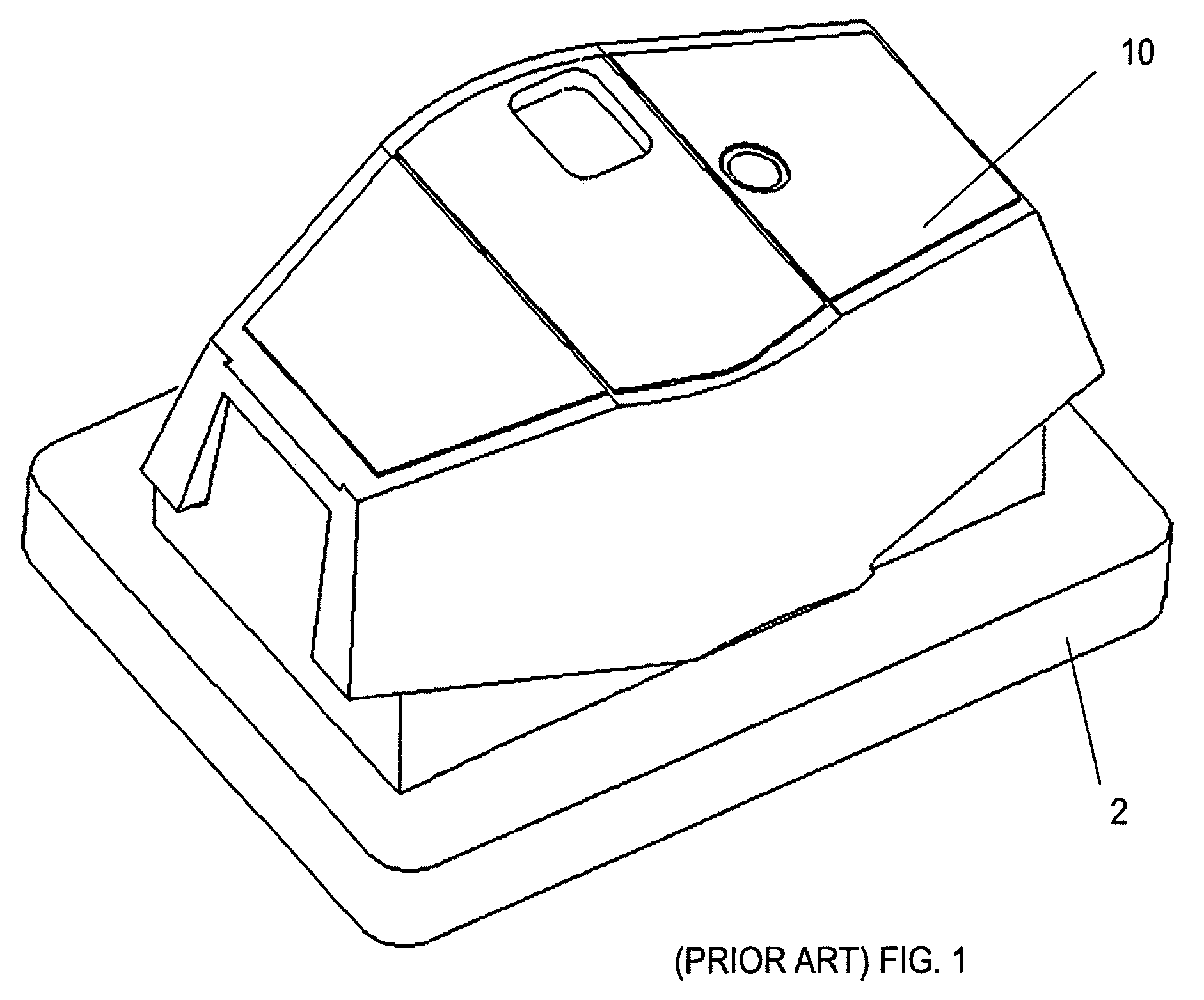
[0018]FIG. 1 of the accompanying drawings depicts schematically a prior art plastics scale model army tank turret 10 sitting upon an inner die 2. The inner die 2 provides no relevant surface detail as it merely defines the basic inner hollow shape of the turret 10. The outer surface of the turret 10 shows surface detail of low-level intricacy.

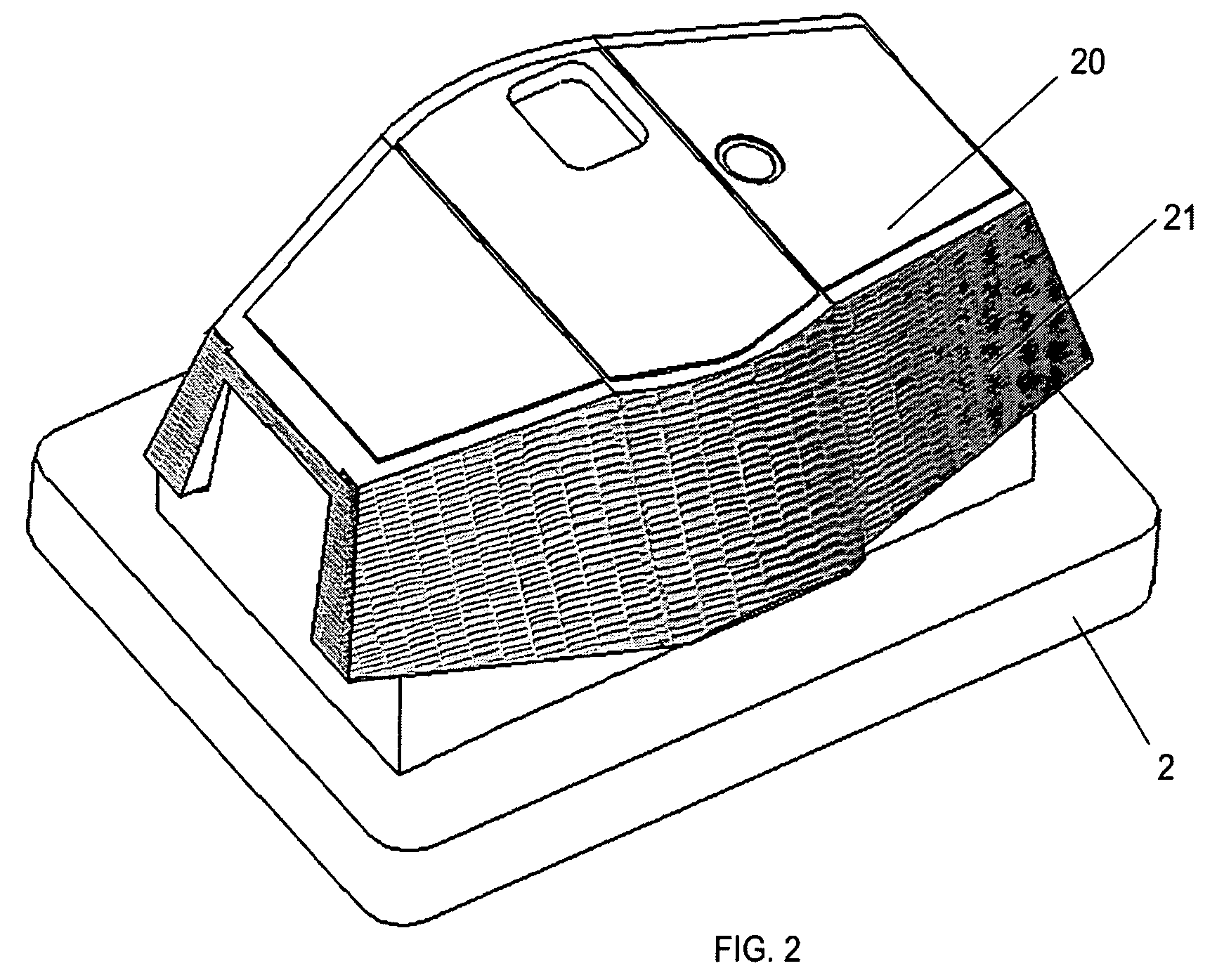
[0019]FIG. 2 depicts schematically a plastics scale model World War II German army tank turret 20 sitting upon an inner die 2. The inner die 2 is for all intents and purposes the same as that depicted in FIG. 1. The outer surface of the turret 20 shows areas 21 of intricate surface detail as provided herein and mimicking the full-scale army tank turret's “Zimmerit paste” anti-mine, camouflage detail. In 1943, the German chemical company Zimmer produced a combination of materials including barium sulphate, polyvinyl acetate, ochre pigment, saw dust and zinc sulphide. This would create a paste that would, when spread over a ferrous surface, preve...


PUM

PropertyMeasurementUnit
areaaaaaaaaaaa
surface textureaaaaaaaaaa
surface featuresaaaaaaaaaa

Abstract

A die for moulding a plastics part includes a cavity defining an overall shape of the part and having a surface-textured insert for providing an area upon the moulded plastics part having intricate surface detail.

Description

BACKGROUND OF THE INVENTION[0001]The present invention relates to plastics moulding. More particularly, although not exclusively, the invention relates to a technique for achieving intricate surface detail in parts of a moulded plastics scale model kit.[0002]Plastics model kits have been known for many years to comprise a “skeleton” of numbered parts to be individually removed to be glued together in accordance with an instruction sheet to form a scale model. Similar skeletons of parts are also provided for purposes other than assembling plastics models—such as for example in the provision of multiple small finished parts like toy figures or components used in other fields.[0003]The known technique of forming such a skeleton of parts is to provide a pair of opposed dies which cooperate to define flow tracks and a plurality of cavities into which the plastics material flows from the flow tracks. The material from which the dies are made is limited in its ability to provide intricate ...

Claims


Application Information

Patent Timeline
Patent Type & Authority Patents(United States)
IPC IPC(8): B41B11/54B29CB29C33/12B29C33/42B29C33/46B29C45/14B29C45/26B29C45/36B29C45/37
CPCB29C45/372B29C45/2673Y10S425/057
Inventor MAK, SHU-KEUNG
Owner DRAGON MODELS LIMITED
Why Eureka
Try Eureka