Lamp device

Inactive Publication Date: 2007-03-20
KUO BENNY L
View PDF9 Cites 12 Cited by
  • Summary
  • Abstract
  • Description
  • Claims
  • Application Information

AI Technical Summary

Benefits of technology

[0005]Therefore, the object of the present invention is to provide a lamp device that is operable so as to change orientation of a lamp unit thereof and that can be easily activated.

Problems solved by technology

As such, the conventional lamp device cannot project a light beam in a desired direction, and is inconvenient to use.

Method used


Image

  • Lamp device
  • Lamp device
  • Lamp device

Examples


Embodiment Construction

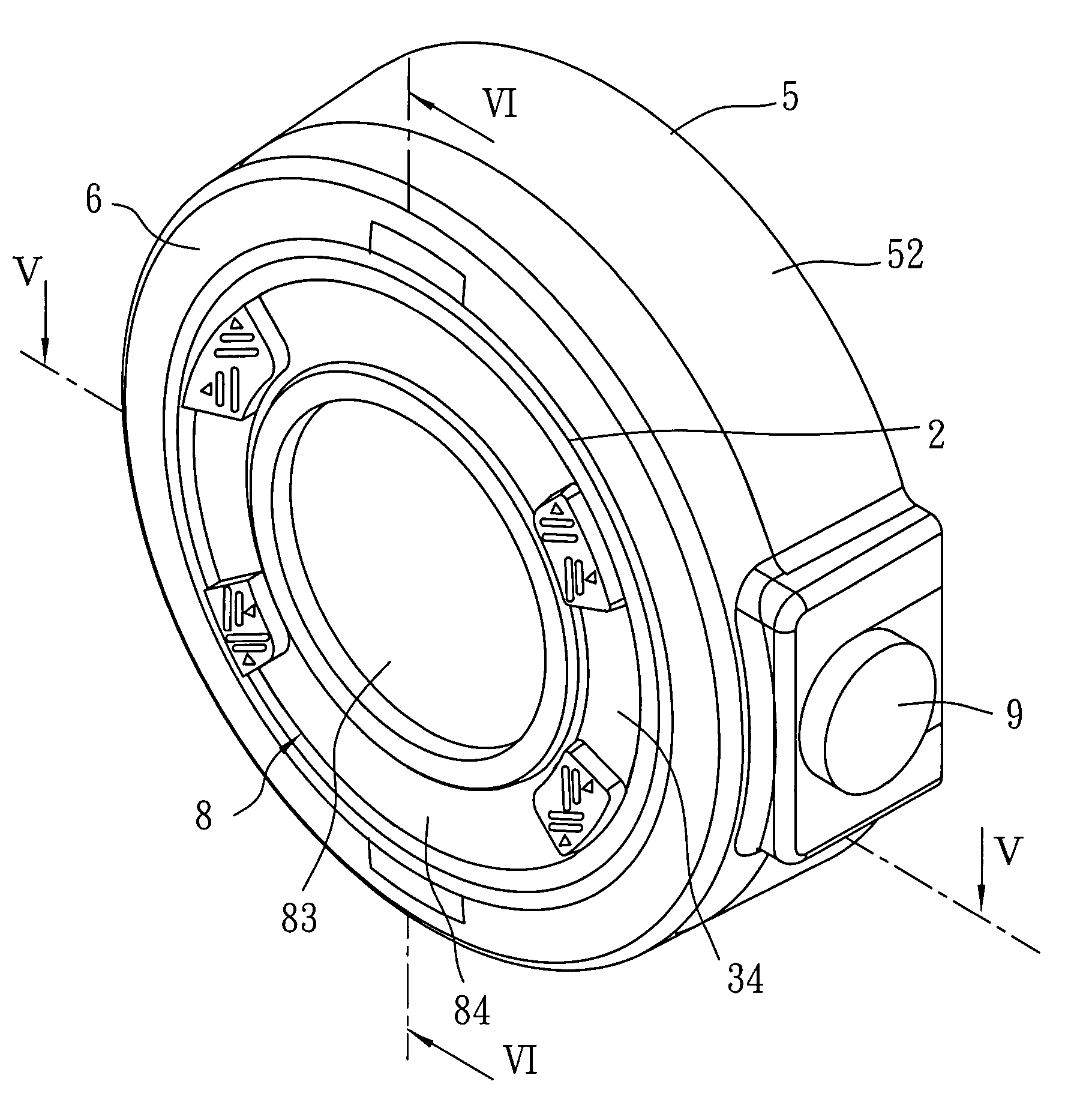
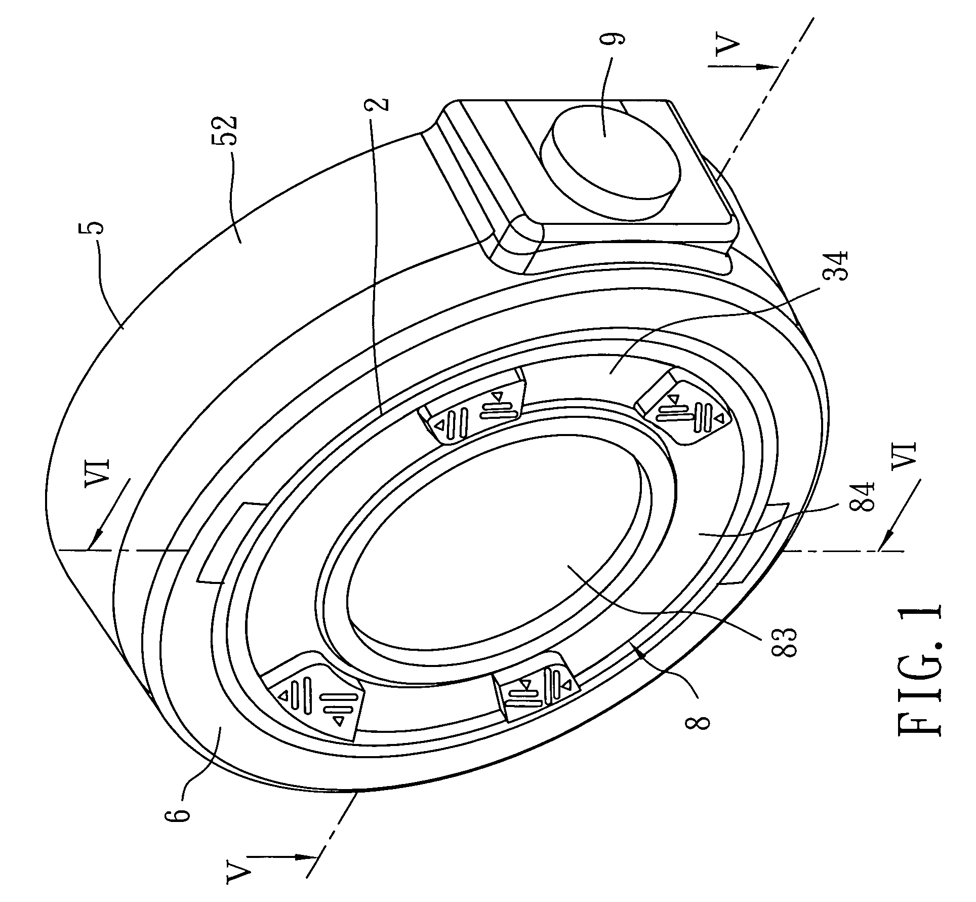
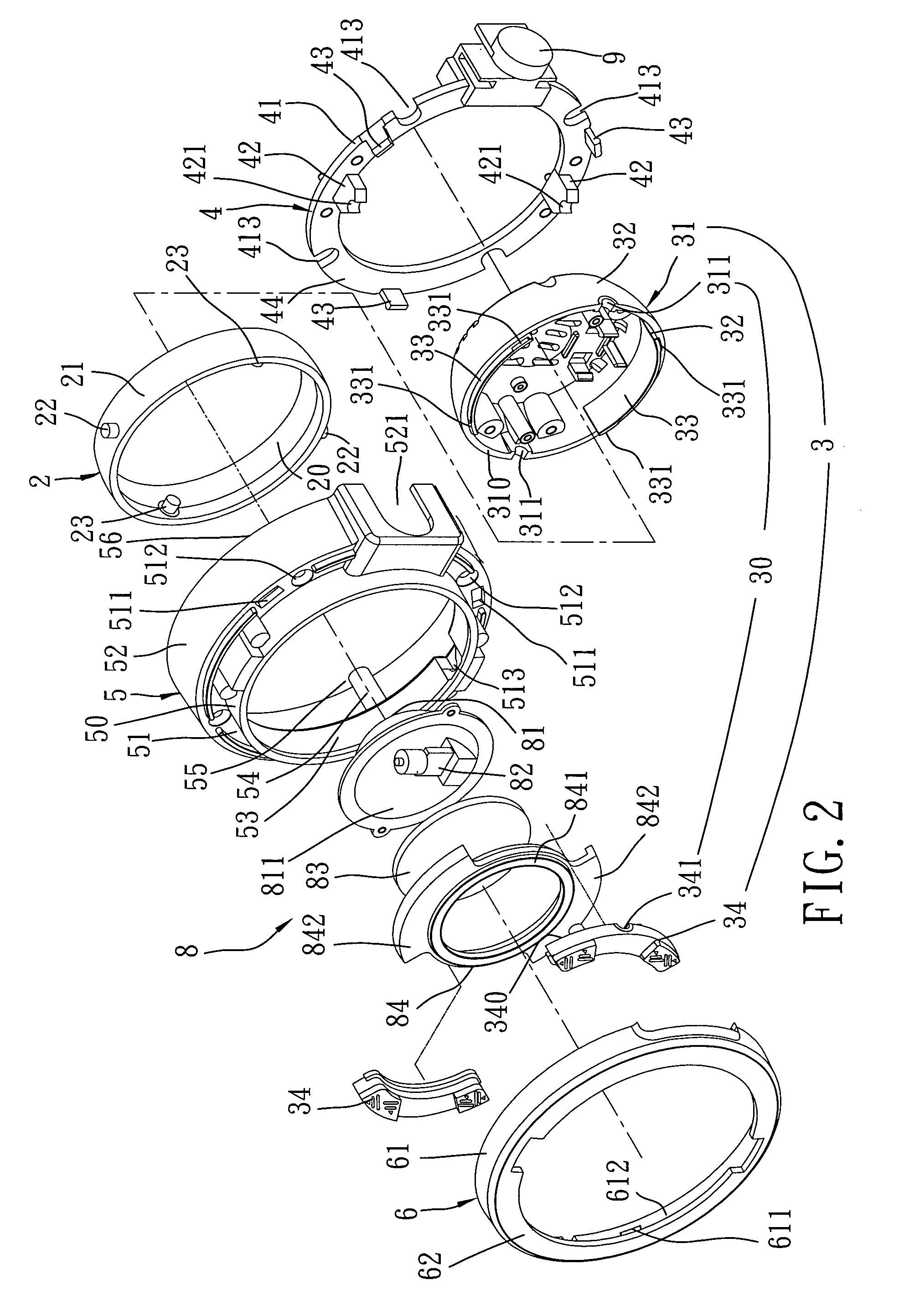
[0019]Referring to FIGS. 1, 2, 5 and 6, the preferred embodiment of a lamp device according to the present invention is shown to include a main sleeve 5, a rear connecting ring 4, a pivot ring 2, a lamp-mounting unit 3, a lamp unit 8, a front decorative ring 6, and an activating unit 9. In this embodiment, the lamp device is adapted to be partly embedded in a wall (not shown).

[0020]The main sleeve 5 has opposite front and rear axial ends 55, 56. In this embodiment, the main sleeve 5 has a smaller-diameter front end portion 50, a larger-diameter rear end portion 52 having an inner diameter larger than that of the front end portion 50, and an intermediate shoulder portion 51 interconnecting the front and rear end portions 50, 52. The front end portion 50 has an annular inner surface 53 formed with opposite recesses 513 that are disposed adjacent to the front axial end 55 of the main sleeve 5. The intermediate shoulder portion 51 has an annular rear surface formed with a plurality of h...


PUM


Abstract

A lamp device includes a pivot ring disposed in a main sleeve and formed with two aligned first pivot shafts that extend radially and outwardly away from each other and that are mounted rotatably between the main sleeve and a rear connecting ring such that the pivot ring is pivotable relative to an assembly of the main sleeve and the rear connecting ring about the first pivot shafts. A lamp-mounting unit is disposed in the main sleeve, and is rotatable about two aligned second pivot shafts formed on the pivot ring and extending inwardly and radially toward each other and perpendicular to the first pivot shafts. A lamp unit is mounted fixedly on the lamp-mounting seat such that an assembly of the lamp-mounting seat and the lamp unit is pivotable relative to the pivot ring about the second pivot shafts.

Description

BACKGROUND OF THE INVENTION[0001]1. Field of the Invention[0002]The invention relates to a lamp device, more particularly to a lamp device that is to be partly embedded in a wall and that is operable so as to change orientation of a lamp unit thereof.[0003]2. Description of the Related Art[0004]A conventional lamp device, which is to be partly embedded in a wall or a ceiling, is used for projecting a light beam therefrom in a fixed direction. Activation of the conventional lamp device is controlled by an external control switch connected electrically thereto via wirings. As such, the conventional lamp device cannot project a light beam in a desired direction, and is inconvenient to use.SUMMARY OF THE INVENTION[0005]Therefore, the object of the present invention is to provide a lamp device that is operable so as to change orientation of a lamp unit thereof and that can be easily activated.[0006]According to the present invention, a lamp device comprises:[0007]a main sleeve having opp...

Claims


Application Information

Patent Timeline
IPC IPC(8): B60Q3/04
CPCB60Q3/0253F21V21/30B60Q3/0286B60Q3/44B60Q3/76
Inventor KUO, BENNY L.
Owner KUO BENNY L
Why Eureka
Try Eureka