Optical transceiving system with frame synchronization and optical receiving apparatus

Active Publication Date: 2012-09-27
NEC CORP
View PDF4 Cites 2 Cited by
  • Summary
  • Abstract
  • Description
  • Claims
  • Application Information

AI Technical Summary

Benefits of technology

[0012]It is an object of the present invention to provide a frame synchronization technology which makes it easy to activate a frame synchronization established state even if bit errors are produced over a transmission link.

Problems solved by technology

According to this proposed technology, however, it is difficult to see if the transmission data contain many errors.
As the error rate of optical fiber transmission link 40 increases, the probability that synchronizing words contain bit errors becomes higher, making it time-consuming to establish frame synchronization.

Method used


Image

  • Optical transceiving system with frame synchronization and optical receiving apparatus
  • Optical transceiving system with frame synchronization and optical receiving apparatus
  • Optical transceiving system with frame synchronization and optical receiving apparatus

Examples


exemplary embodiment 1

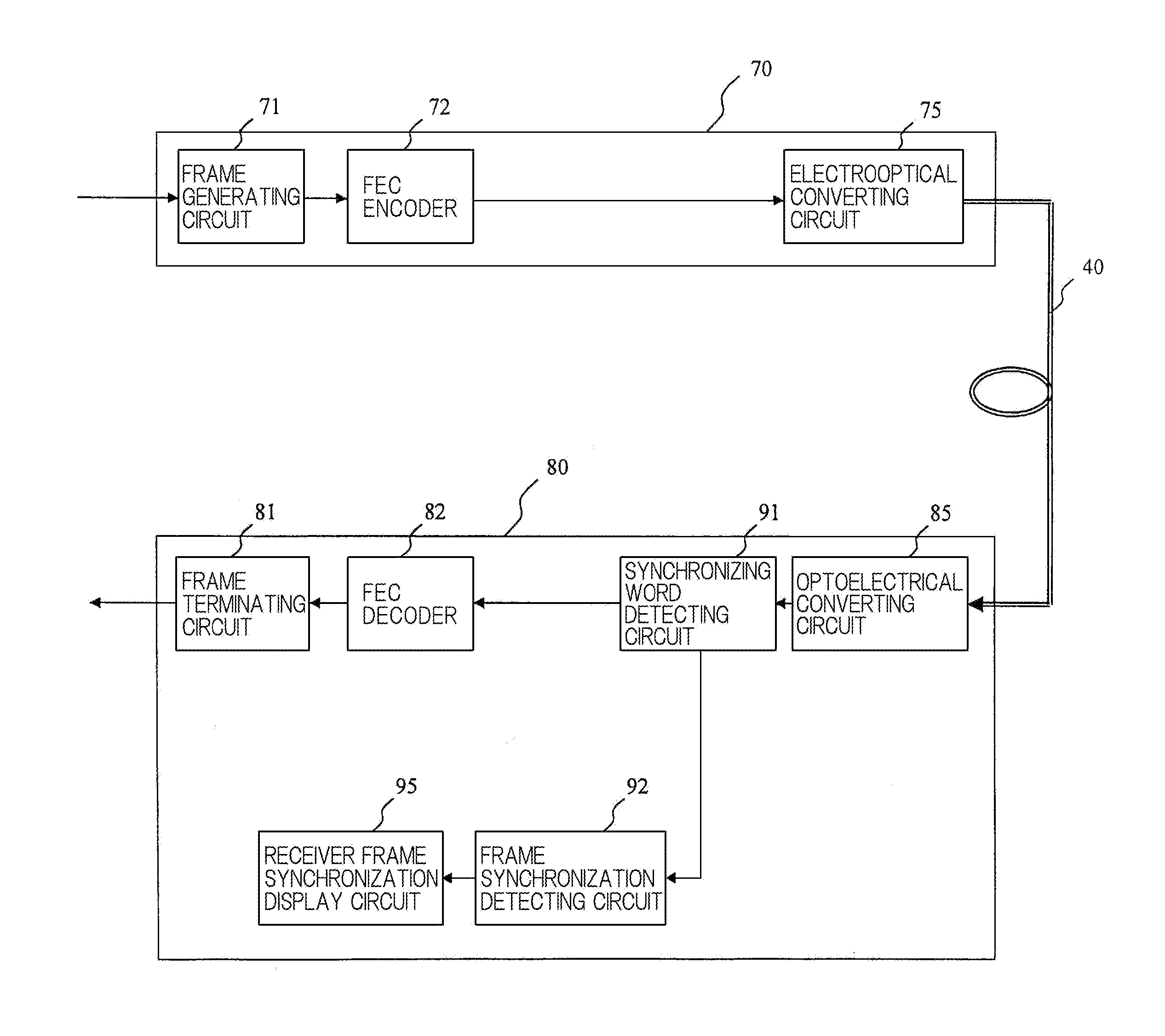
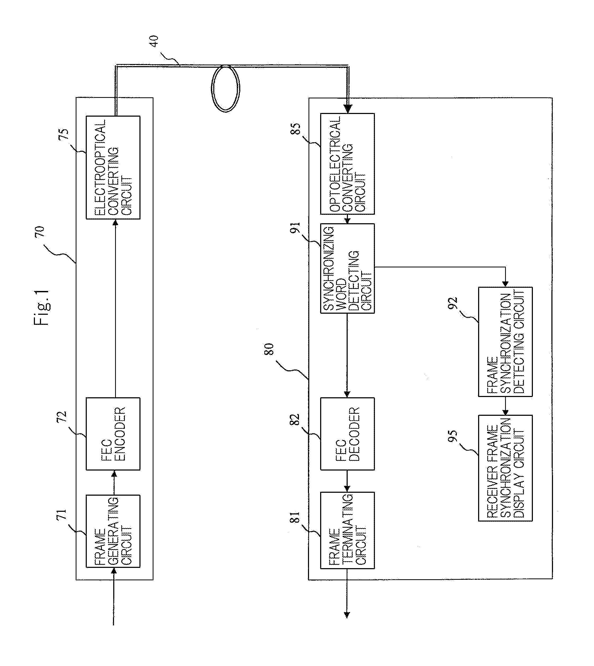
[0033]FIG. 4 is a block diagram showing the configuration of an optical transceiving system according to the present exemplary embodiment of the present invention. As shown in FIG. 4, the optical transceiving system includes optical transmitting apparatus 10 and optical receiving apparatus 20 which are connected to each other by optical fiber transmission link 40. Optical fiber transmission link 40 may have optical repeaters or the like.

[0034]Optical transmitting apparatus 10 includes frame generating circuit 11, FEC (Forward Error Correction) encoder 12, and electrooptical converting circuit 15.

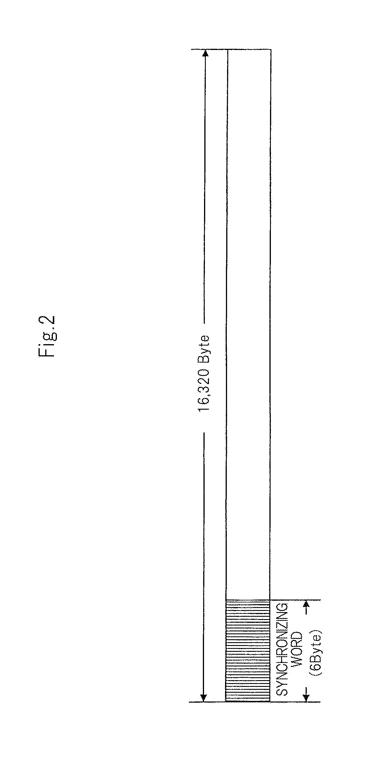
[0035]Frame generating circuit 11 is supplied with an electric signal as a data signal. Frame generating circuit 11 adds a synchronizing word for establishing frame synchronization to the supplied data signal, to generate and output a frame-added electric signal.

[0036]FEC encoder 12 adds an error correcting code to the frame-added electric signal from frame generating circuit 11, thereby gen...

exemplary embodiment 2

[0064]FIG. 6 is a flowchart of an optical transceiving method according to the present exemplary embodiment of the present invention. The optical transceiving method includes a transmitting sequence (P11 through P13) for transmitting an optical signal and a receiving sequence (P14 through P20) for receiving an optical signal.

[0065]According to the transmitting sequence, a synchronizing word is added to a data signal, generating a frame-added electric signal (frame generating process P11). Thereafter, an error correcting code is added to the frame-added electric signal, generating an error-correcting-code-added electric signal (FEC encoding process P12). The error-correcting-code-added electric signal is then converted into an optical signal, which is transmitted (electrooptical converting process P13).

[0066]According to the receiving sequence, the optical signal transmitted in electrooptical converting sequence P13 is received and optoelectrically converted to reproduce the error-co...

exemplary embodiment 3

[0072]FIG. 7 is a block diagram showing the configuration of an optical transceiving system according to the exemplary embodiment of the present invention. The optical transceiving system shown in FIG. 7 is different from the optical transceiving system shown in FIG. 4 in that optical transmitting apparatus 10 further includes scrambler 13 added between FEC encoder 12 and electrooptical converting circuit 15, and optical receiving apparatus 20 further includes descrambler 23 added between pre-stage synchronizing word detecting circuit 31 and FEC decoder 22.

[0073]Scrambler 13 of optical transmitting apparatus 10 scrambles the error-correcting-code-added electric signal from FEC encoder 12 by using a pseudo-random signal. The scrambling process is effective to prevent the error-correcting-code-added electric signal from having a succession of identical signs such as “0” or “1” or to equalize the probabilities that “0” and “1” will appear. Descrambler 23 of optical receiving apparatus ...


PUM


Abstract

An optical receiving apparatus with frame synchronization technology which makes it easy to activate a frame synchronization established state even if bit errors are produced over a transmission link. The apparatus includes: an optoelectrical converting circuit; a pre-stage synchronizing word detecting circuit; a decoder; a post-stage frame synchronization detecting circuit; and a receiver frame synchronization display output circuit.

Description

BACKGROUND OF THE INVENTION[0001]1. Field of the Invention[0002]The present invention relates to an optical transceiving system and an optical receiving apparatus.[0003]2. Description of the Related Art[0004]At present, there have been proposed a variety of technologies for increasing the reliability of transmission links in the field of optical communications. For example, a technology has been proposed for operating a plurality of frame synchronizing circuits parallel to each other and establishing frame synchronization with any one of the frame synchronizing circuits (see, for example, JP11-331140A). According to this proposed technology, however, it is difficult to see if the transmission data contain many errors.[0005]FEC (Forward Error Correction) processes with a high error correction capability have been made practically feasible by the advances of digital circuit technologies. Therefore, attention has been paid to a technology for increasing the reliability of transmission ...

Claims


Application Information

Patent Timeline
IPC IPC(8): H04B10/00H04B10/06H04B10/556
CPCH04B10/69H04B10/40H04L7/048
Inventor TAKAHASHI, TSUGIO
Owner NEC CORP
Why Eureka
Try Eureka