Patch panel system

a patch panel and panel technology, applied in the direction of coupling device connection, instruments, nuclear elements, etc., can solve the problems of patch panel port knowledge, patch panel port modification, and existing commercially available patch cords without the adapter contact needed

Inactive Publication Date: 2007-03-20
SIEMON
View PDF8 Cites 212 Cited by
  • Summary
  • Abstract
  • Description
  • Claims
  • Application Information

AI Technical Summary

Problems solved by technology

One difficulty experienced with patch panels is knowing which port of the patch panel is connected to which port on the active equipment.
A drawback to the system of U.S. Pat. No. 6,574,586 is that modifications must be made to the plug (i.e., the addition of an adapter jacket) and the outlet (i.e., the addition of the adapter board) to determine port connectivity.
Furthermore, existing commercially available patch cords do not include the adapter contact needed to engage the socket contact.

Method used


Image

  • Patch panel system
  • Patch panel system
  • Patch panel system

Examples


Embodiment Construction

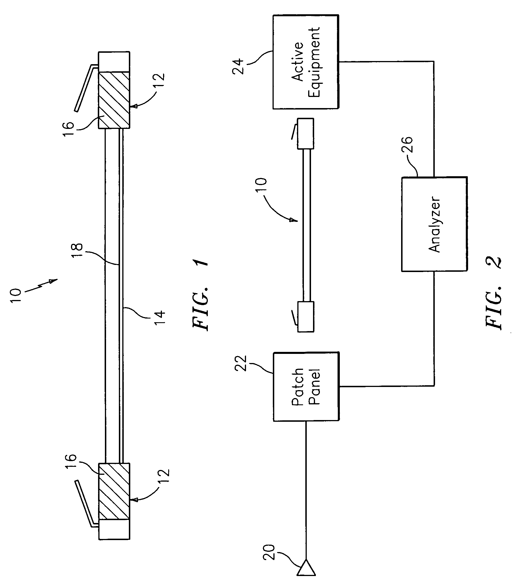
[0012]FIG. 1 depicts an exemplary patch cord for use in embodiments of the invention. The patch cord 10 includes plugs 12 connected by cabling 14. Each plug includes metallic screen 16. In one embodiment, cabling 14 includes 8 copper wires corresponding to 4 twisted pairs. A conductor 18 connects the metallic screens 16 on the plugs 12. Conductor 18 may be a cable screen (e.g., braid or foil shield) or may be a single wire. The screened patch cord, referred to as ScTP, is readily available and may be similar to the screened MC6™ patch cord available from The Siemon Company. Other shielded patch cords may be used such as fully shielded patch cords referenced in the art as FTP patch cords.

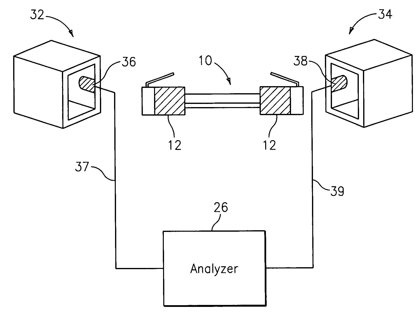
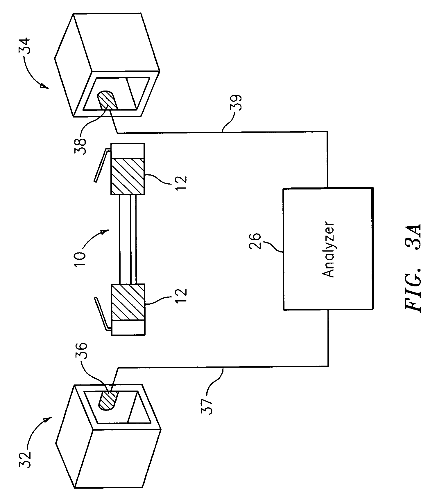
[0013]FIG. 2 depicts an exemplary patch panel system in an embodiment of the invention. FIG. 2 depicts a telecommunications outlet 20 connected to a patch panel 22 by horizontal cabling. The patch panel 22 is connected to a device such as active equipment 24 which may be a server, a hub, a switch, et...


PUM


Abstract

A patch panel system including a patch panel having a first outlet including a first conductive tab and a device having a second outlet including a second conductive tab. A patch cord has a first plug having a first screen for contacting the first tab and a second plug having a second screen for contacting the second tab. The patch cord includes a conductor electrically connecting the first screen and the second screen. An analyzer is electrically connected to the first tab and detects a connection between the first tab and the second tab along the conductor.

Description

CROSS REFERENCE TO RELATED APPLICATION[0001]This application claims the benefit of U.S. provisional patent application Ser. No. 60 / 537,946, filed Jan. 20, 2004, the entire contents of which are incorporated herein by reference.BACKGROUND OF THE INVENTION[0002]Patch panels are often used to provide an interconnection between telecommunication outlets and active equipment. One difficulty experienced with patch panels is knowing which port of the patch panel is connected to which port on the active equipment. One solution to this problem is disclosed in U.S. Pat. No. 6,574,586, the contents of which are incorporated herein by reference. U.S. Pat. No. 6,574,586 discloses a system in which an adapter jacket having an external contact is placed on the plug. Outlets include an adapter board having a socket contact. The socket contacts are wired to an analyzer which then can determine which sockets are connected by patch cords by applying a signal to each socket contact.[0003]A drawback to ...

Claims


Application Information

Patent Timeline
Patent Type & Authority Patents(United States)
IPC IPC(8): G01R31/04G21C17/00H01R29/00
CPCH01R13/6691
Inventor VELLECA, FRANKSIEMON, JOHN A.
Owner SIEMON
Why Eureka
Try Eureka