
Protective bus interface and method

a protection bus and interface technology, applied in the field of interfaces, can solve the problems of electrical or logical failure, poor speed performance of improved reliability, and shut down the entire system, and achieve the effect of preventing potentially faulty commercial peripherals

Inactive Publication Date: 2007-03-20
III HLDG 12 LLC
View PDF30 Cites 62 Cited by
  • Summary
  • Abstract
  • Description
  • Claims
  • Application Information

AI Technical Summary

Benefits of technology

The patent text describes a method and apparatus for preventing faulty commercial peripherals and I / O devices from disabling the bus to which they are connected. This is achieved by using a bus isolation apparatus that includes a controller, processing element, and memory. The apparatus allows for the separation of I / O and bus messages, preventing faulty devices from disabling the bus. Additionally, the method includes steps of determining if a message is for output or input, and temporarily storing and checking it before transferring it to the bus only if valid. This prevents a failed device from disabling the bus.

Problems solved by technology

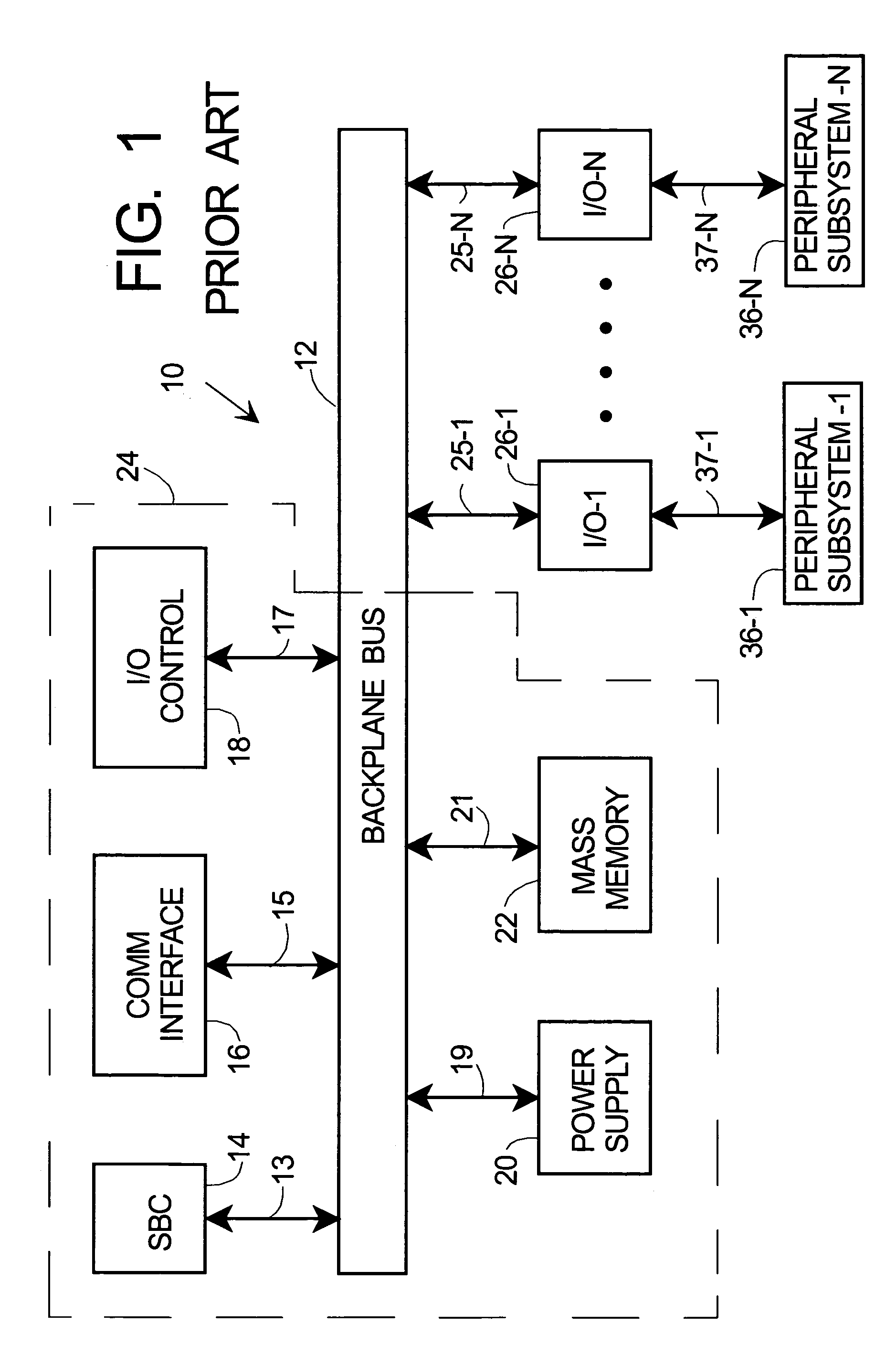
However, a disadvantage of the arrangement of system 10 of FIG. 1 is that an electrical or logical failure in any of I / O-1 to I / O-N can shut down the entire system if it disables bus 12.
The price paid for improved reliability is generally poorer speed performance.
Another disadvantage of the serial bus is that there are generally not as many choices of I / O devices available for serial bus systems.
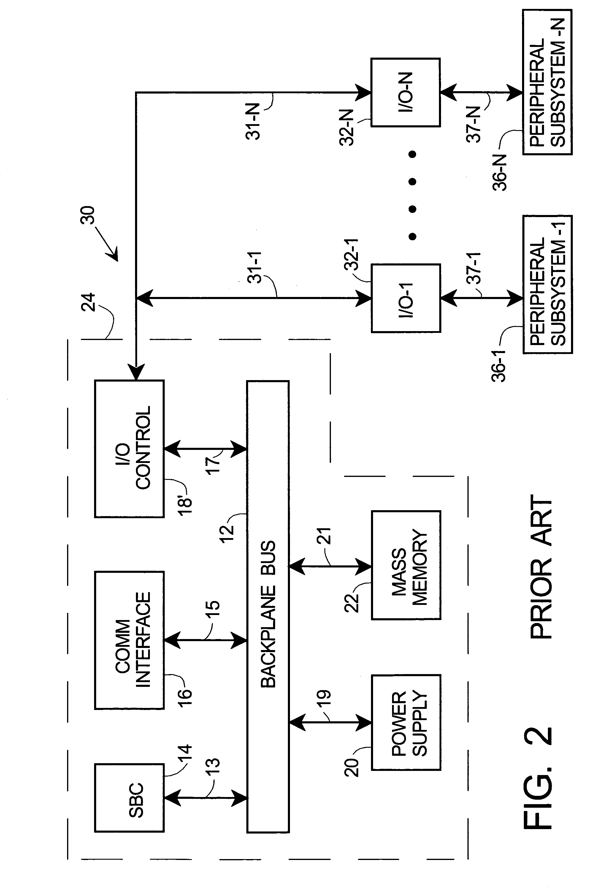
The need for custom designs significantly increases the initial and ongoing cost of overall system 40.
Most importantly, advantage cannot easily be taken of the many commercially available I / O elements and peripheral subsystems that do not provide for bus isolation.
In addition, failures within an individual isolator and / or its associated custom I / O can still prevent bus 12 from communicating with other peripherals or preclude other peripherals from communicating with bus 12.
Thus, prior art system 40 is only a partial and undesirably costly solution to the problem of providing high speed and fault-tolerant bus-peripheral interfaces.

Method used


Image

  • Protective bus interface and method
  • Protective bus interface and method
  • Protective bus interface and method

Examples


Embodiment Construction

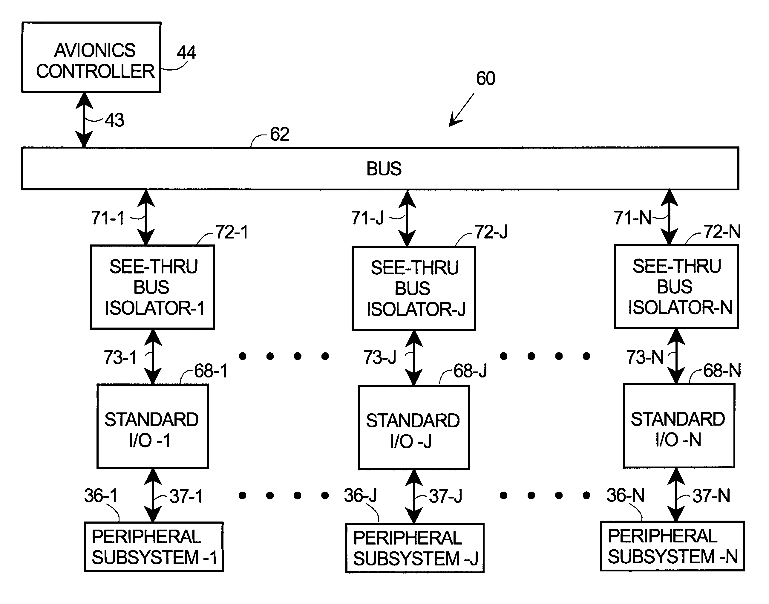
[0020]The following detailed description is merely exemplary in nature and is not intended to limit the invention or the application and uses of the invention. Furthermore, there is no intention to be bound by any expressed or implied theory presented in the preceding technical field, background, brief summary or the following detailed description. For convenience of description, FIGS. 4–FIG. 7 are described in terms of a system used in flight vehicles, e.g., for use in connection with avionics systems, but this is not intended to be limiting. Persons of skill in the art will understand based on the description herein that the present invention applies to any type of electronic system with a processing core (e.g., but not limited to sub-system 24 of FIGS. 1–3) that needs to reliably communicate with various peripheral subsystems 1 through N via I / O ports I / O-1 . . . I / O-J . . . I / O-N, where 1≦J≦N.

[0021]Referring now to FIG. 4, avionics controller 44 in FIGS. 4–7 is analogous to elec...


PUM


Abstract

Method and apparatus are provided for preventing faulty commercial-off-the-shelf (COTS) peripherals or I / Os from disabling the bus to which they are connected. The apparatus has isolators coupled to the bus and the I / Os. A controller is coupled between the interfaces, a processor and memory, operating such that an I / O cannot transfer data to the bus without permission from the bus. Isolation memory keeps I / O and bus messages separate. I / O messages are checked before being sent to the bus. The method comprises: determining if there is a message for the peripheral, temporarily storing the message, determining if the message is for output or input, and if for output, sending it to the peripheral, and if for input, requesting and receiving it from the peripheral, temporarily storing and checking it, and transferring it to the bus only if valid. This prevents a failed I / O or peripheral from disabling the bus.

Description

TECHNICAL FIELD[0001]The present invention generally relates to interfaces between various portions of an electronic data system, and more particularly relates to protective bus interfaces and methods therefore.BACKGROUND[0002]It is common in the electronic arts to use buses to interconnect various portions of an electronic system. In general a bus comprises one or more conductors (electrical or optical) along which digital signals are carried from one part of an electronic system to another, according to specific protocols defined by the system and bus architecture. For example, in computers, avionics, and other computer based instrumentation and control systems, a “back-plane” bus is often used.[0003]FIG. 1 is a simplified electrical schematic diagram of a prior art electronic system 10 employing a back-plane bus 12. System 10 has a single board computer (SBC) 14, communication interface16, I / O control 18, power supply 20, and mass memory 22. These elements, enclosed within outlin...

Claims


Application Information

Patent Timeline
Patent Type & Authority Patents(United States)
IPC IPC(8): G06F11/00G06F13/40
CPCG06F13/4063
Inventor FLETCHER, MITCHELL S.ALEJANDRO, PETER G.BLACK, RANDALL H.GREGG, MICHAEL R.REVELLE, VICTOR S.
Owner III HLDG 12 LLC
Learn More