Method and device for displaying a moon image cycle, in particular for a watch

a technology of moon image cycle and display device, which is applied in the field of methods and devices for displaying moon image cycle, can solve the problems of display losing all appeal and their evolution remains quite inaccurate, and achieve the effect of reducing the number of lines of separation and reducing the number of light and dark fields on the indicator

Active Publication Date: 2007-03-27
THE SWATCH GRP RES & DEVELONMENT LTD
View PDF9 Cites 11 Cited by
  • Summary
  • Abstract
  • Description
  • Claims
  • Application Information

AI Technical Summary

Benefits of technology

[0014]It will be noted that a basic idea of the present invention consists in using the same line of separation, located on the mobile indicator, for form different successive images of the moon by slightly moving this line to pass to the next image. This is how it becomes possible to reduce the number of lines of separation in relation to the number of different images that one wishes to display, and thus reduce the number of light and dark fields on the indicator. Consequently, the fields and the aperture allowing them to appear can be relatively large in relation to the size of the indicator and that of the dial.

Problems solved by technology

These images conform better to reality than those of conventional devices, but their evolution remains quite inaccurate, since the display only changes approximately every two days.
If one desired more frequent updating, the number of images on the disc would have to be doubled and their size thus reduced so much that the display would lose all appeal.

Method used


Image

  • Method and device for displaying a moon image cycle, in particular for a watch
  • Method and device for displaying a moon image cycle, in particular for a watch
  • Method and device for displaying a moon image cycle, in particular for a watch

Examples


first embodiment

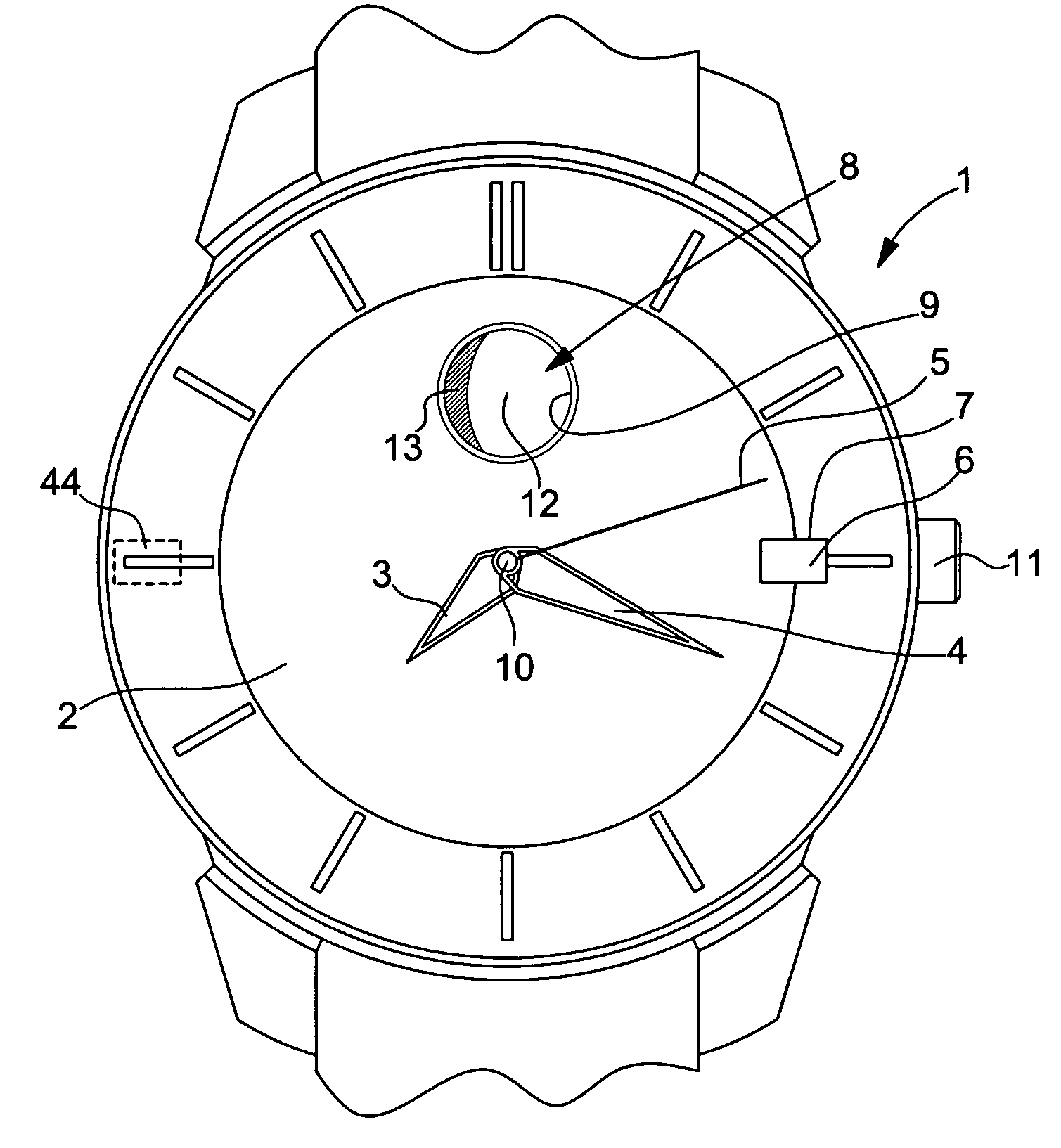
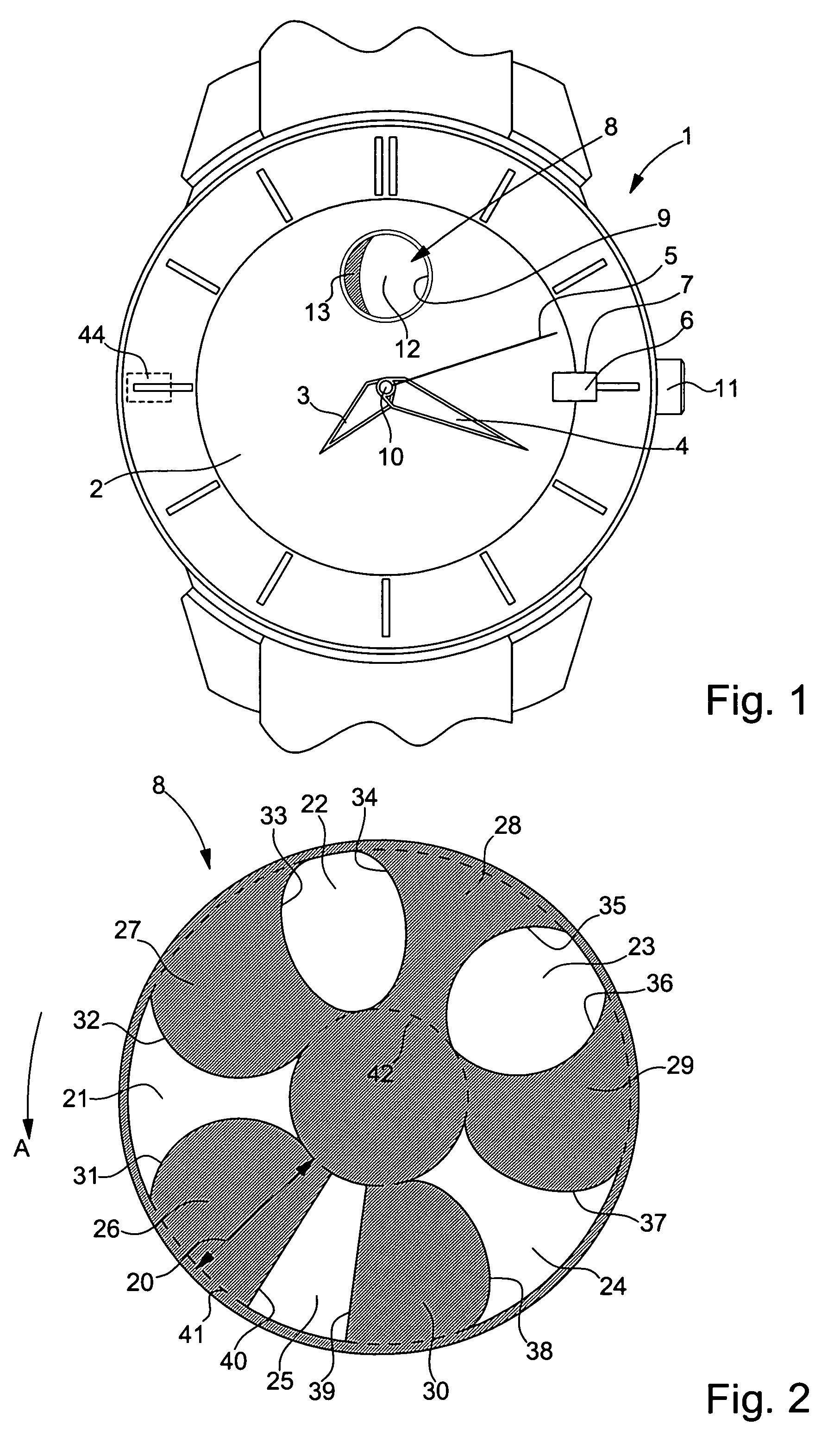
[0023]In a first embodiment which will now be described with reference to FIGS. 1 to 3, watch 1 is a multifunction electronic watch and its display members are actuated by means of electric stepping motors. In particular, moon indicator disc 8 is provided with a drive mechanism (not shown) having its own stepping motor, with a reducing gear large enough that, for example, about 1000 steps of the motor are necessary to produce one complete revolution of disc 8. Date disc 6 is driven by means of a motor that is dedicated thereto, whereas hands 3 to 5 can be driven by means of one or several other motors.

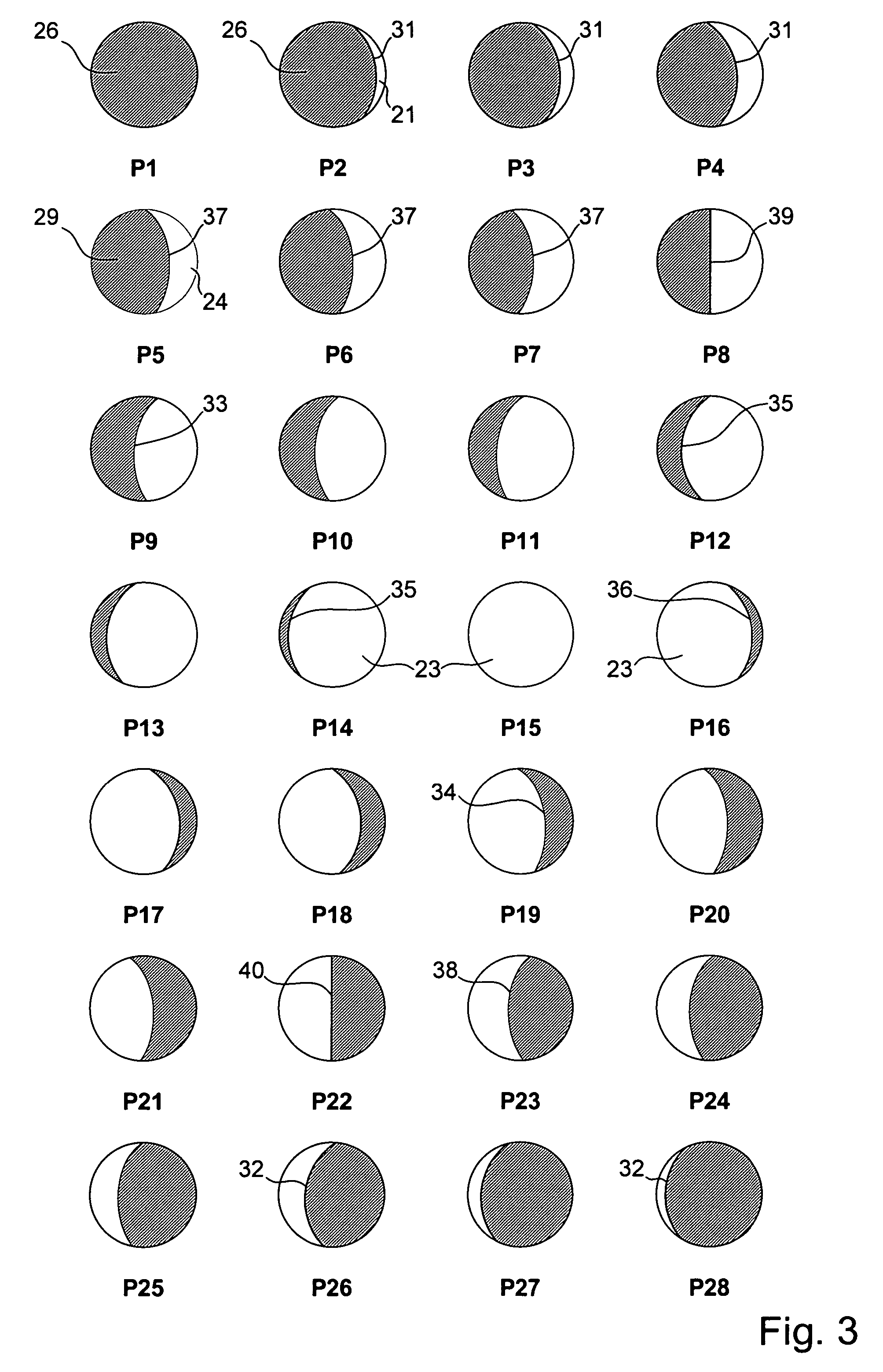
[0024]In aperture 9, the user of the watch sees a circular portion of disc 8, which shows the current appearance of the moon seen from the earth and comprises, most of time, a light part 12 and a dark part 13 respectively showing the illuminated part and the non-illuminated part of the moon. Parts 12 and 13 are delimited by a line of separation that can be rectilinear or more or less c...

second embodiment

[0036]In a second embodiment that will now be described with reference to FIGS. 1 and 4 to 7, watch 1 is a watch with a mechanical movement and the movement drives its display members. In particular, the moon indicator disc 8, whose top face is visible in FIG. 5, is provided with a drive mechanism 75 shown in FIGS. 6 and 7. FIG. 4 shows that there is further provided an indication of the age of the moon. Thus, close to circular aperture 9 which is the same as in FIG. 1, dial 2 comprises an elongated aperture 45 edged with a scale 46 from, for example, 1 to 29 or 30. In order to reduce the length of the aperture, half of scale 46 is distributed over one edge of the aperture, and the other half along the opposite edge. A small zone of disc 8 appears in this aperture and comprises an index 47 which points over the half of scale 46 concerned.

[0037]In a similar manner to that of the preceding example, but with a slightly different geometry, there is provided on disc 8 a region 50 in the ...


PUM


Abstract

In order to display images true to the real appearance of the moon during a lunation, particularly in a watch, there is provided a rotating indicator disc (8) arranged behind a circular aperture of a dial and comprising an annular region (20) subdivided into alternatively light (21–25) and dark (26–30) fields by lines of separation (31–40) having different shapes, which can appear in succession in the aperture. The drive means impart primary movements on the indicator disc (8), each of which is large enough to replace one of the lines of separation by another in the aperture, and smaller secondary movements, to produce small movements of the line of separation inside the aperture. This allows a new image of the moon to be given every day, true to reality, with a restricted number of light and dark fields on the indicator disc and a particularly large aperture in relation to the size of the dial. A version with electric driving is disclosed and a version driven by a mechanical watch movement.

Description

[0001]This application claims priority from European Patent Application No. 04016085.5 filed Jul. 8, 2004, the entire disclosure of which is incorporated herein by reference.BACKGROUND OF THE INVENTION[0002]The present invention concerns a method for displaying a cycle of successive images of the moon during a lunation in a circular aperture of a dial by means of a mobile indicator arranged behind the aperture and having, on the face thereof that appears in the aperture, lines of separation of different shapes between light fields and dark fields for showing respectively the illuminated part and the dark part of the moon seen from the earth.[0003]The invention also concerns a device for displaying a cycle of successive images of the moon during a lunation in a circular aperture of a dial, particularly for implementing the aforementioned method, comprising a mobile indicator arranged behind said aperture and driving means for moving the indicator step by step so that different parts ...

Claims


Application Information

Patent Timeline
Patent Type & Authority Patents(United States)
IPC IPC(8): G04B19/26
CPCG04B19/268
Inventor BORN, JEAN-JACQUESMEYLAN, FREDERIC
Owner THE SWATCH GRP RES & DEVELONMENT LTD
Why Eureka
Try Eureka