
Portable circuit interrupter tester and method

a tester and circuit interrupter technology, applied in the field of portable circuit interrupter testers, can solve the problems of overload circuit interrupter trip, inconvenient breaker tripping, high current surge, etc., and achieve the effect of optimum accuracy, durability and safety, and simple, inexpensive and portable technology

Inactive Publication Date: 2007-04-03
HURWICZ MAXIM D
View PDF34 Cites 34 Cited by
  • Summary
  • Abstract
  • Description
  • Claims
  • Application Information

AI Technical Summary

Benefits of technology

The device efficiently and repeatedly tests circuit breakers' instantaneous tripping capabilities without damaging the device or wiring, ensuring the circuit breaker operates within specifications and safely identifies faulty breakers, reducing the risk of overheating and arcing.

Problems solved by technology

Instantaneous circuit interrupters supply a means of interrupting current that might be dangerous to people or the wiring circuit, as in the case of a short-circuit overcurrent that could result in a fire or electrocution.
First when there is a short circuit causing a sudden very high surge of current.
Second when there is an ongoing load that draws more current than the interrupter is rated for.
This should trip the overload circuit interrupter.
Third, when there is some current being drawn off to ground.
It would be inconvenient to have the breaker tripping at these times. Thus, circuit breakers have an overload circuit interrupter employing a thermal element that allows small overcurrents for limited time periods.
Conventional circuit breaker testing devices suffer by only testing either circuit breakers or GFIs.
(l) potential damage to wiring and the device in the event of the circuit breaker not tripping off;

Method used


Image

  • Portable circuit interrupter tester and method
  • Portable circuit interrupter tester and method
  • Portable circuit interrupter tester and method

Examples


Embodiment Construction

[0079]In the following detailed description of the preferred embodiments, reference is made to the accompanying drawings that form a part hereof, and in which are shown by way of illustration specific embodiments in which the invention may be practiced. It is understood that other embodiments may be utilized and structural changes may be made without departing from the scope of the present invention.

[0080]The leading digit(s) of reference numbers appearing in the Figures generally corresponds to the Figure number in which that component is first introduced, such that the same reference number is used throughout to refer to an identical component that appears in multiple Figures. Signals and connections may be referred to by the same reference number or label, and the actual meaning will be clear from its use in the context of the description.

[0081]Another further embodiment of the present invention includes multiple selectable load circuits, for example, by having a switch that sele...


PUM


Abstract

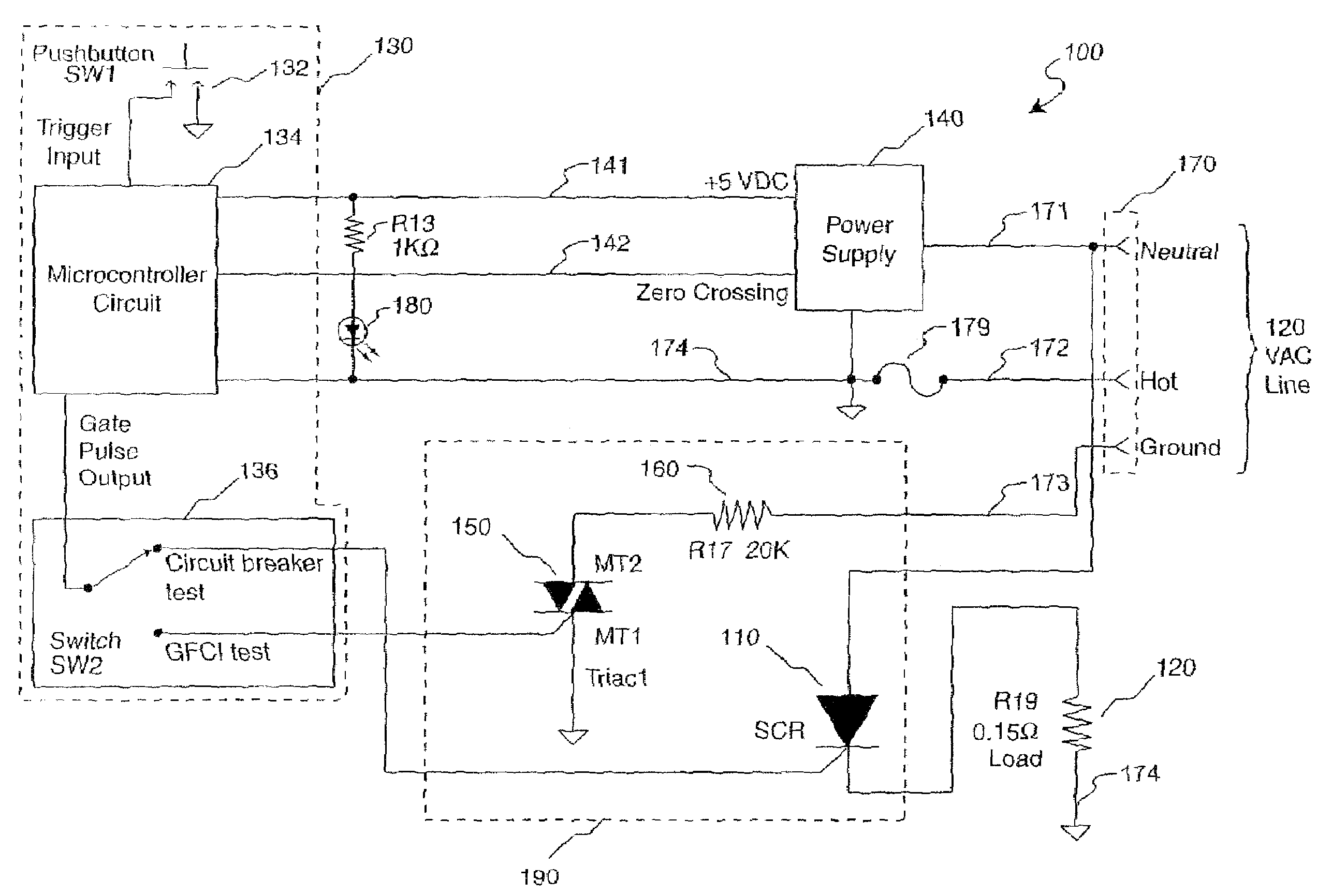
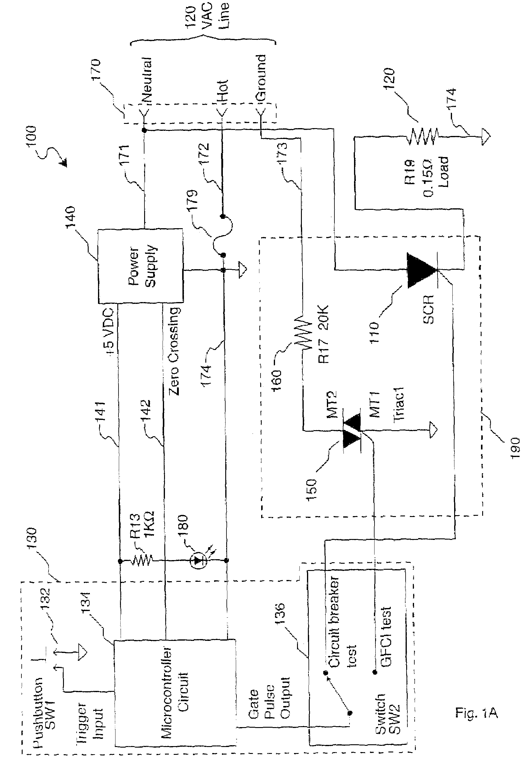
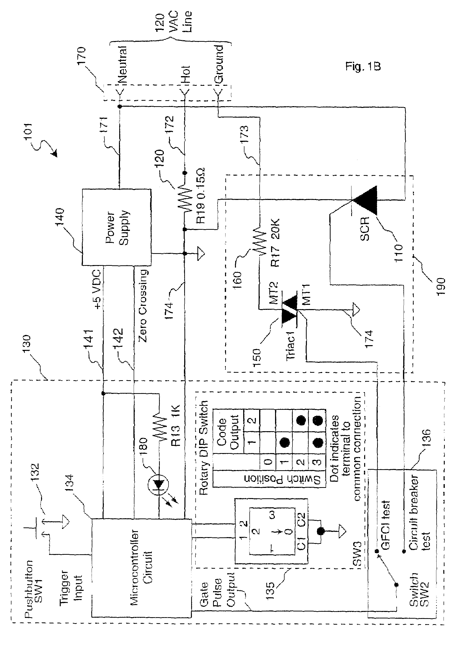
A portable circuit interrupter shutoff testing device and method, including a high current switch controlled by a timing circuit that allows current to flow through the switch and a small series resistance (in order to trip the instantaneous-trip function of the interrupter, as opposed to the overload-trip) for a short time period relative to the sine wave of the electrical power. A button activates the timing circuit which in turn activates the switch and current flows limited by the internal resistor of the device. By limiting the on time of the device to one or a few half cycles, the user can test if the circuit interrupter responds as quickly as specified by the manufacturer. A method includes receiving a stimulation indication, and selectively connecting an electrical load to wires connected to the circuit interrupter, wherein the electrical load is sufficient to trigger the instantaneous-trip function of the circuit-interrupter.

Description

CROSS-REFERENCE TO RELATED APPLICATIONS[0001]This application is a continuation of prior application U.S. patent application Ser. No. 10 / 293,524, filed Nov. 12, 2002 now U.S. Pat. No. 7,173,428; which claims benefit of U.S. Provisional Patent Application No. 60 / 337,650, filed Nov. 13, 2001; each which is hereby incorporated by reference in its entirety.FIELD OF THE INVENTION[0002]This invention relates to electrical circuitry testers, including circuit-interrupter testers. More particularly, it relates to the method and apparatus for testing and breaking instantaneous circuit interrupters in electrical boxes and outlets.BACKGROUND OF THE INVENTION[0003]Instantaneous circuit interrupters (also called instantaneous circuit breakers) and overload circuit interrupters (also called overload circuit breakers) are important components used to protect electrical circuits. Often, an instantaneous circuit interrupter and an overload circuit interrupter are packaged in a single device simply c...

Claims


Application Information

Patent Timeline
Patent Type & Authority Patents(United States)
IPC IPC(8): G01R31/327G01R31/333
CPCG01R31/3272G01R31/3333
Inventor HURWICZ, MAXIM D.
Owner HURWICZ MAXIM D
Learn More