Backlight module

a backlight module and light guide plate technology, applied in the direction of instrumentation, lighting and heating apparatus, planar/plate-like light guides, etc., can solve the problem of decreasing brightness and achieve the effect of uniform reflected ligh

Active Publication Date: 2007-04-17
CORETRONIC
View PDF4 Cites 31 Cited by
  • Summary
  • Abstract
  • Description
  • Claims
  • Application Information

AI Technical Summary

Benefits of technology

[0006]An object of the present invention is to provide a side light-type backlight module which is provided with increased light reflection area and uniform reflection of light.
[0008]According to another aspect of the present invention, aside-light backlight module comprises: a light guide plate including at least one first sidewall which is provided with a reflection layer, and two opposite second sidewalls perpendicular to said first sidewall; and at least one light sources disposed at one of the second sidewalls and projecting light rays onto the reflection layer along a direction oblique to the reflection layer, wherein the reflection area of the backlight module and uniformity of the reflected light may be enhanced through the pre-designed synchronous emission and projection of light onto the reflection layer by the light sources and through the reflection of light by the reflection layer.

Problems solved by technology

However, such a backlight module encounters a problem in that there are dark regions 121 between two adjacent bright regions 120 which are substantially elliptical and which extend in a direction toward the side 12 from the corresponding light source element 11 and that brightness tends to decrease from the side 10 toward the side 12.

Method used


Image

  • Backlight module
  • Backlight module
  • Backlight module

Examples


Embodiment Construction

[0017]Before the present invention is described in greater detail, it should be noted that same reference numerals have been used to denote like elements throughout the specification.

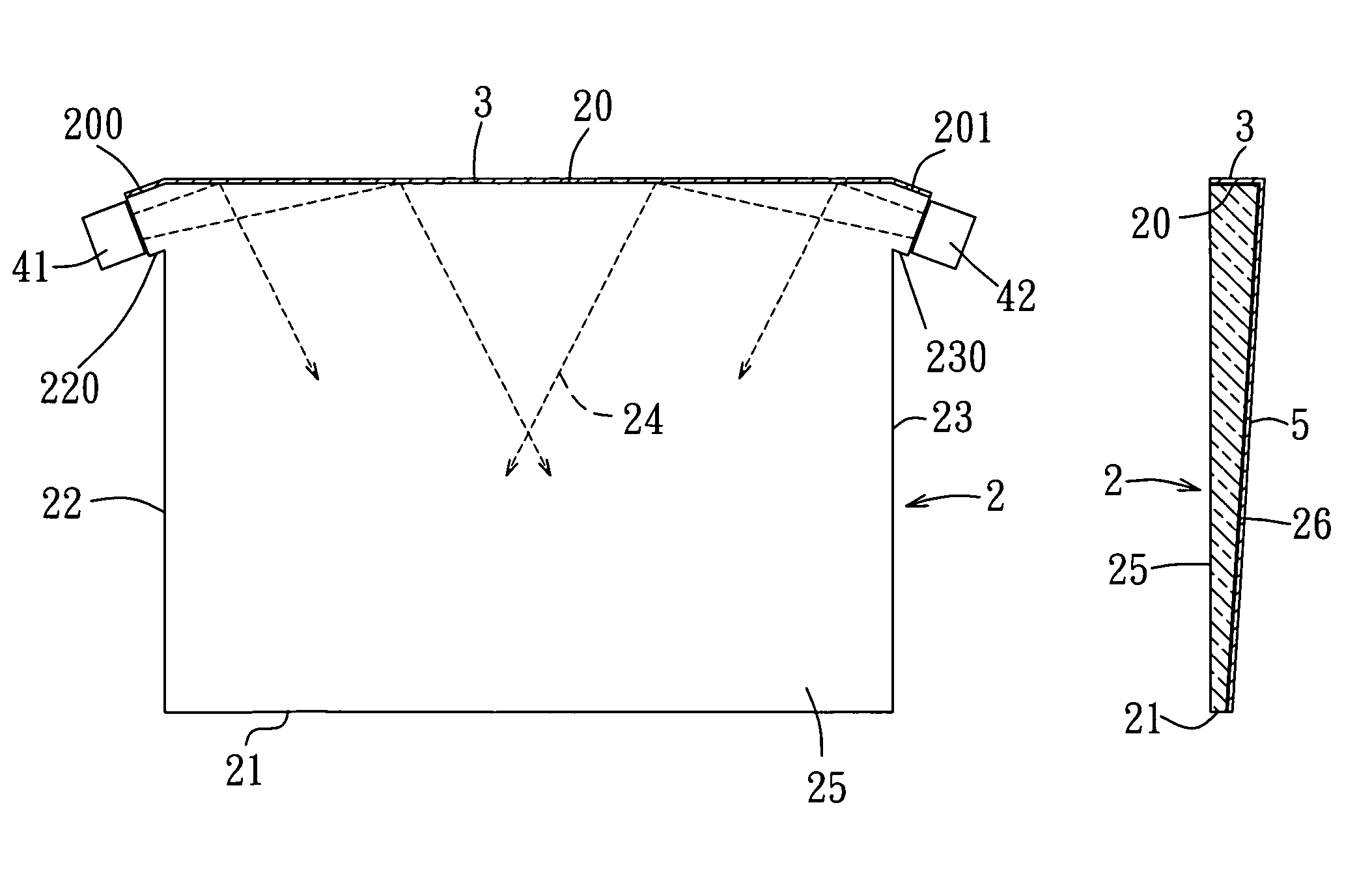
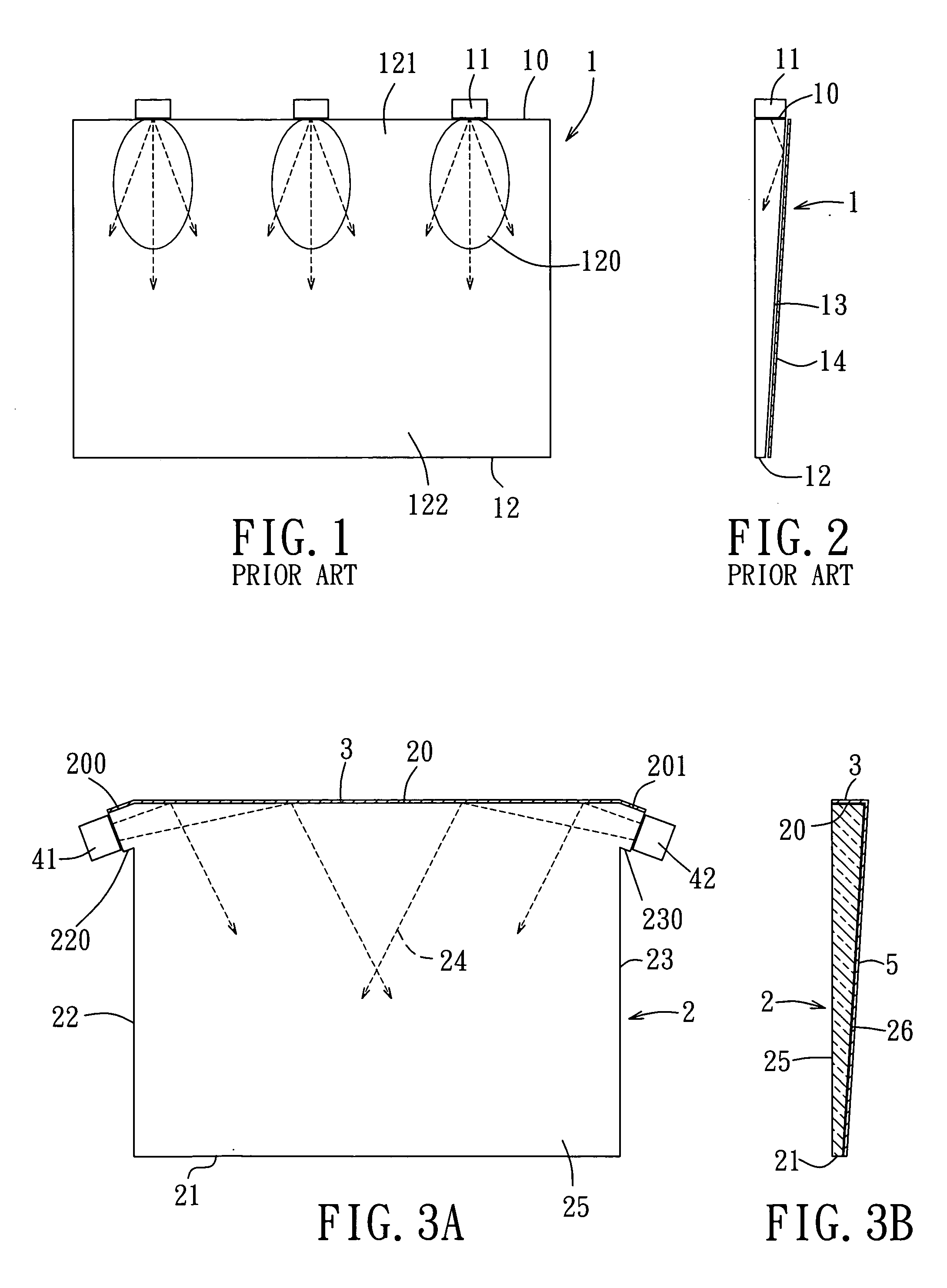
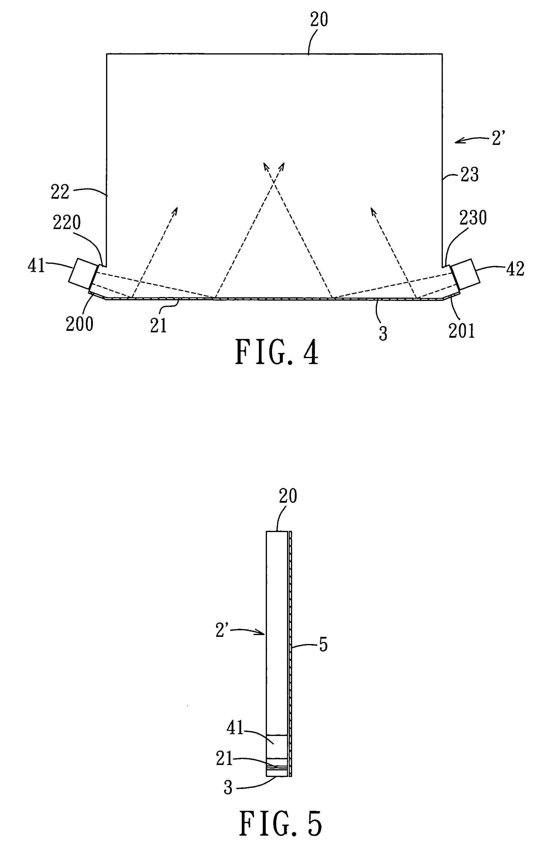
[0018]Referring to FIGS. 3A and 3B, there is shown the first preferred embodiment of a side-light type backlight module according to the present invention which includes a light guide plate 2. The light guide plate 2 includes opposite first and second faces 25, 26 (i.e., front and back walls 25, 26), two opposite first sidewalls 20, 21 (i.e. top and bottom sidewalls 20, 21), and two opposed second sidewalls 22, 23 (i.e. left and right sidewalls 22, 23). The first or front face 25 is used as a light exit face. The first and second sidewalls 20, 21, 22, 23 are connected to and extend between the first and second faces 25, 26. The second sidewalls 22, 23 extend transversely of and interconnect the first sidewalls 20, 21. Preferably, the second sidewalls 22, 23 are perpendicular to the first sidewalls 20, 2...


PUM


Abstract

A backlight module includes a light guide plate which has a first sidewall and two opposite second sidewalls extending transversely of the first sidewalls. The first and second sidewalls interconnect two opposite first and second faces. Alight source is disposed at one of the second sidewalls and projects light rays onto the first sidewall at an oblique angle. A first reflection layer is disposed over the first sidewall, and a second reflection layer is disposed over the second face. Total reflection of light into the light guide plate from the first sidewall and second face increases brightness and enhances evenness of brightness.

Description

CROSS-REFERENCE TO RELATED APPLICATION[0001]This application claims priority from Taiwanese Patent Application No. 93140516, filed on Dec. 24, 2004.BACKGROUND OF THE INVENTION[0002]1. Field of the Invention[0003]This invention relates to a backlight module, more particularly to a light guide plate of a backlight module.[0004]2. Description of the Related Art[0005]Backlight modules have been commonly used in display units of numerous electronic devices, such as mobile phones whose display units are generally used to display communication data or information. As shown in FIGS. 1 and 2, a conventional backlight module includes a light guide plate 1 and a plurality of spaced apart light source elements 11 disposed at one side 10 of the light guide plate 1. The thickness of the light guide plate1 is tapered from the side 10 to the other side 12, and a reflection layer 14 is attached to one surface 13 of the light guide plate 1. The tapered configuration of the light guide plate 1 is used...

Claims


Application Information

Patent Timeline
Patent Type & Authority Patents(United States)
IPC IPC(8): F21V7/04
CPCG02B6/0018G02B6/0068
Inventor CHEN, CHIEN-HSIANGHOU, SHI-CHI
Owner CORETRONIC
Why Eureka
Try Eureka