Device and method for creating hydrodynamic cavitation in fluids

a technology of hydrodynamic cavitation and fluids, applied in the direction of transportation and packaging, process and machine control, instruments, etc., can solve the problems of inability to overcome these limits using traditional technologies, ineffective attempts to overcome these limits, and inability to achieve the effect of overcoming these limits

Inactive Publication Date: 2007-04-24
ARISDYNE STSTEMS INC
View PDF12 Cites 111 Cited by
  • Summary
  • Abstract
  • Description
  • Claims
  • Application Information

AI Technical Summary

Problems solved by technology

Moreover, during the creation of new products and formulations, the challenge often involves the production of two, three, or more complex components in disperse systems containing particle sizes at the submicron level.
Given the ever-increasing requirements placed on the quality of dispersing, traditional methods of dispersion that have been used for decades in technological processes have reached their limits.
Attempts to overcome these limits using these traditional technologies are often not effective, and at times not possible.
Where these bubbles and cavities enter a zone having increased pressure, vapor condensation takes place withing the cavities and bubbles, almost instantaneously, causing the cavities and bubbles to collapse, creating very large pressure impulses.
Such high-impact loads result in the breakup of any medium found near the collapsing bubbles.

Method used


Image

  • Device and method for creating hydrodynamic cavitation in fluids
  • Device and method for creating hydrodynamic cavitation in fluids
  • Device and method for creating hydrodynamic cavitation in fluids

Examples


Embodiment Construction

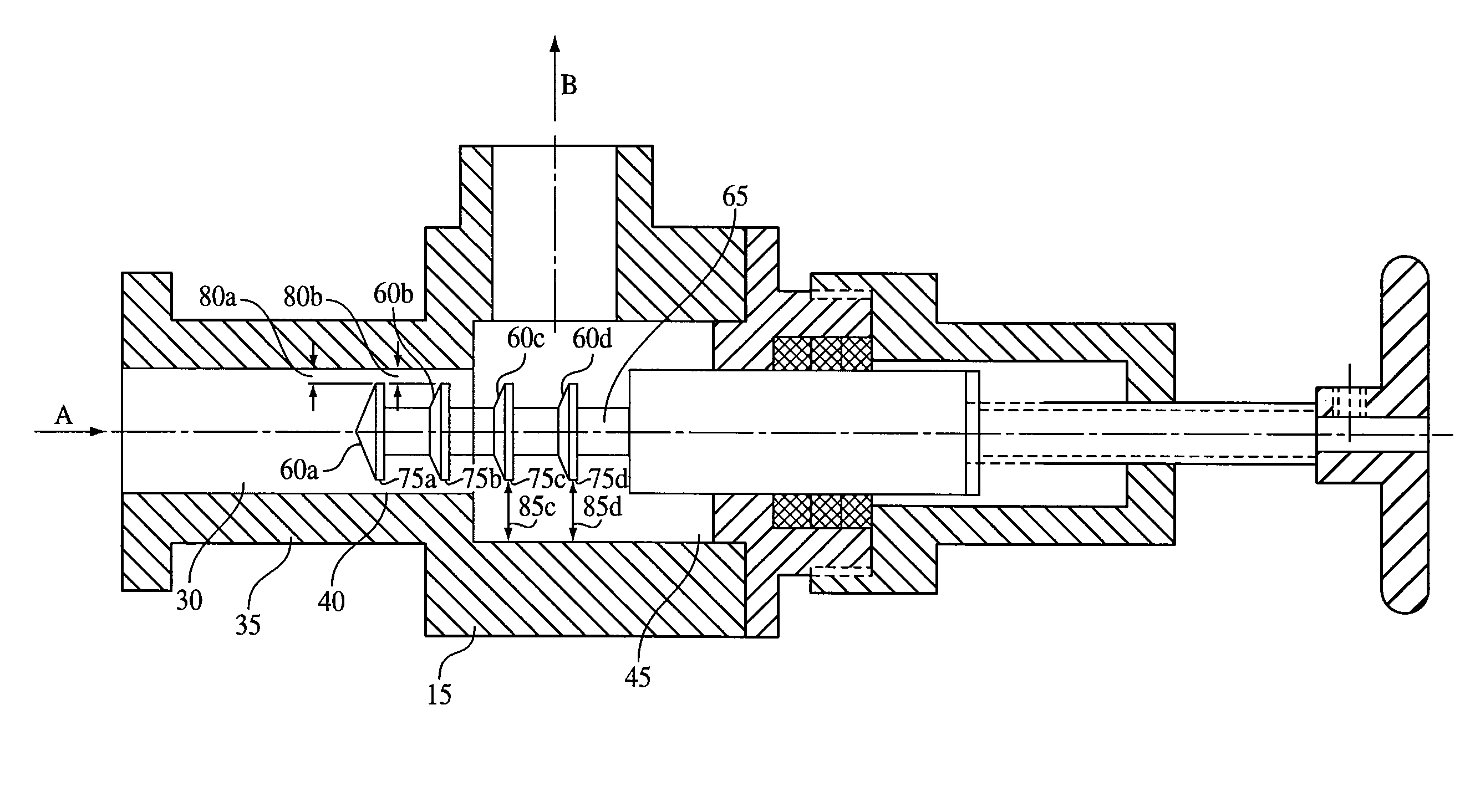
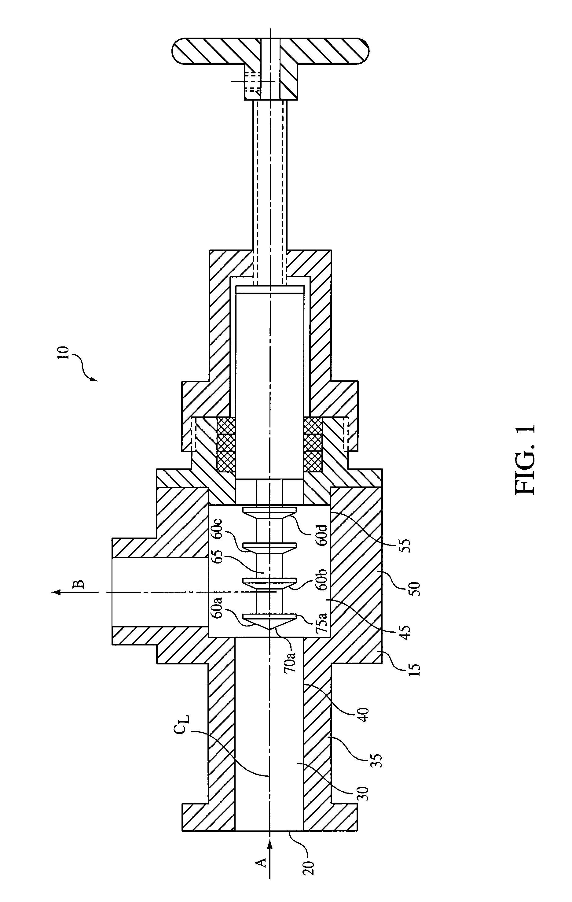
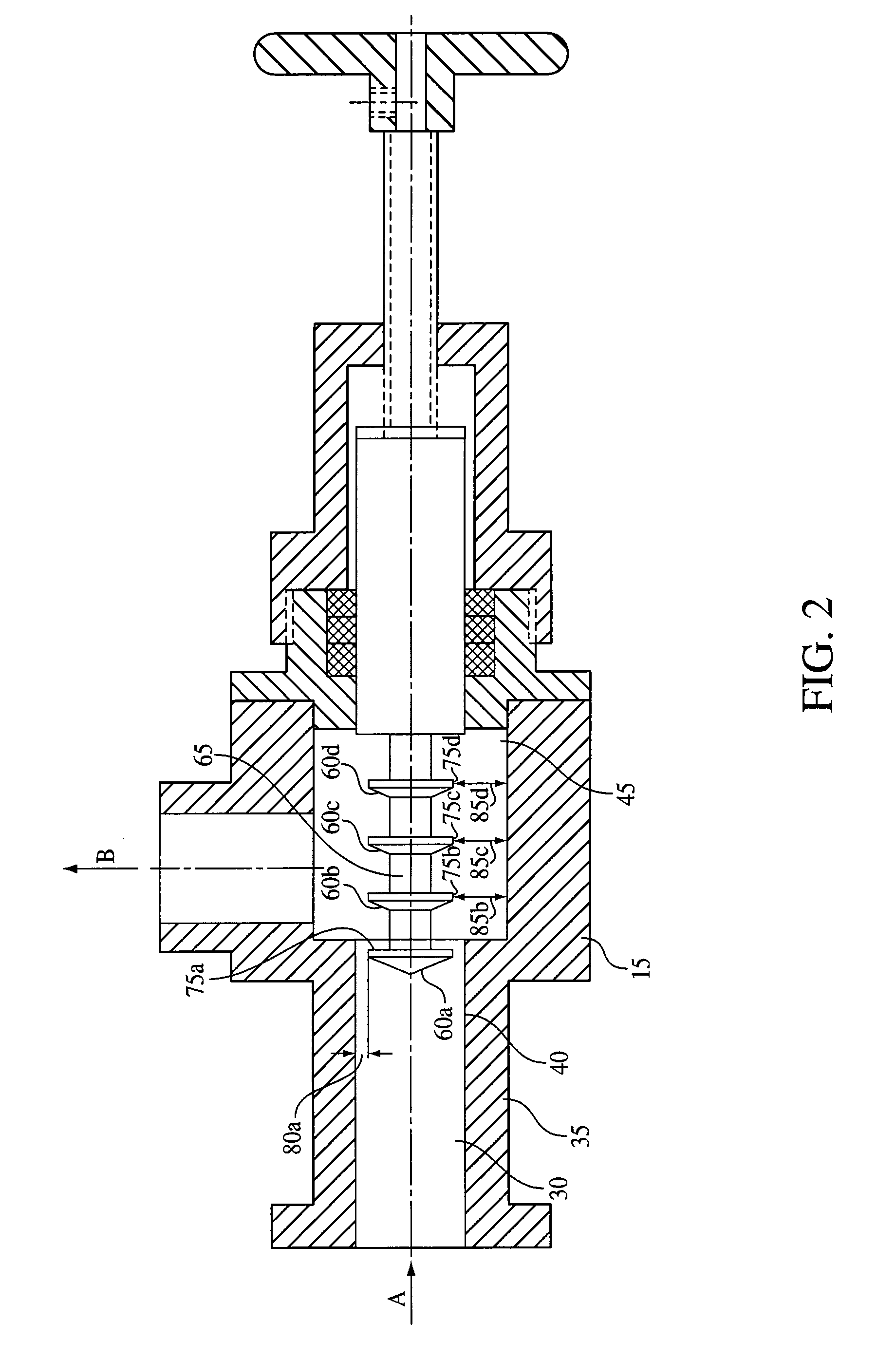
[0012]Illustrated in FIG. 1 is a longitudinal cross-section of one embodiment of a device 10 that can be dynamically configured to generate one or more stages of hydrodynamic cavitation in a fluid.

[0013]In one embodiment, the device 10 can include a flow-through channel or chamber 15 having a centerline CL. The device 10 can also include an inlet 20 configured to introduce a fluid into the device 10 along a path represented by arrow A and an outlet 25 configured to permit the fluid to exit the device 10 along a path represented by arrow B.

[0014]In one embodiment, the flow-through chamber 15 can include an upstream portion 30 that is defined by a wall 35 having an inner surface 40 and a downstream portion 45 that is defined by a wall 50 having an inner surface 55. The upstream portion 30 of the flow-through chamber 15 can have, for example, a circular cross-section. Similarly, the downstream portion 45 of the flow-through chamber 15 can have a circular cross-section. Obviously, it wi...


PUM

PropertyMeasurementUnit
velocityaaaaaaaaaa
velocityaaaaaaaaaa
diametersaaaaaaaaaa

Abstract

A device and method for creating hydrodynamic cavitation in fluid is provided. The device can include a flow-through chamber having a first portion and a second portion, and a plurality of baffles provided within the second portion of the flow-through chamber. One or more of the plurality of baffles can be configured to be selectively movable into the first portion of the flow-through chamber to generate a hydrodynamic cavitation field downstream from each baffle moved into the first portion of the flow-through chamber.

Description

BACKGROUND OF THE INVENTION[0001]One of the most promising courses for further technological development in chemical, pharmaceutical, cosmetic, refining, food products, and many other areas relates to the production of emulsions and dispersions having the smallest possible particle sizes with the maximum size uniformity. Moreover, during the creation of new products and formulations, the challenge often involves the production of two, three, or more complex components in disperse systems containing particle sizes at the submicron level. Given the ever-increasing requirements placed on the quality of dispersing, traditional methods of dispersion that have been used for decades in technological processes have reached their limits. Attempts to overcome these limits using these traditional technologies are often not effective, and at times not possible.[0002]Hydrodynamic cavitation is widely known as a method used to obtain free disperse systems, particularly lyosols, diluted suspension...

Claims


Application Information

Patent Timeline
Patent Type & Authority Patents(United States)
IPC IPC(8): B01F5/06B01F25/46
CPCB01F3/0807B01F3/12B01F5/068B01F5/08B01F5/0662B01F2003/125B01F23/41B01F23/56B01F23/50B01F25/441B01F25/4422B01F25/46
Inventor KOZYUK, OLEG V.
Owner ARISDYNE STSTEMS INC
Why Eureka
Try Eureka