
Computer system

a computer system and computer technology, applied in computing, instruments, electric digital data processing, etc., can solve the problems of user control of video interface, increased emi, and difficulty in considering both emi and output level

Inactive Publication Date: 2007-04-24
SAMSUNG ELECTRONICS CO LTD
View PDF17 Cites 0 Cited by
  • Summary
  • Abstract
  • Description
  • Claims
  • Application Information

AI Technical Summary

Benefits of technology

[0013]Accordingly, it is an aspect of the present invention to provide a computer system which can provide a high-definition picture controlling a video interface.

Problems solved by technology

Such high-frequency RGB signals cause EMI to be increased.
Such a problem arises when the display device for a computer system is replaced by another compatible display device.
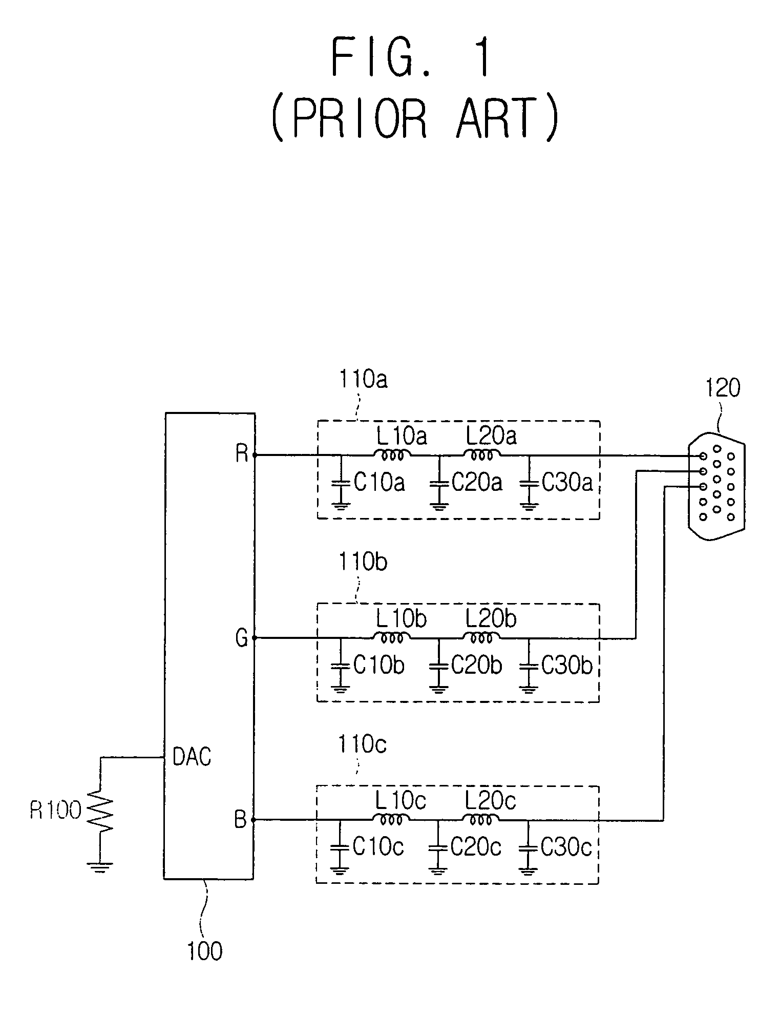
However, in the graphic chipset 100 of the conventional computer system, the resistor R100 and the EMI filters 110a˜110c are invariably connected, so that a user is not allowed to control the video interface in order to improve the picture quality.
Further, it is difficult to consider both the EMI and the output level while constructing the EMI filters.

Method used


Image

  • Computer system
  • Computer system
  • Computer system

Examples


Embodiment Construction

[0025]Reference will now be made in detail to the embodiments of the present invention, examples of which are illustrated in the accompanying drawings, wherein like reference numerals refer to the like elements throughout. The embodiments are described below to explain the present invention by referring to the figures.

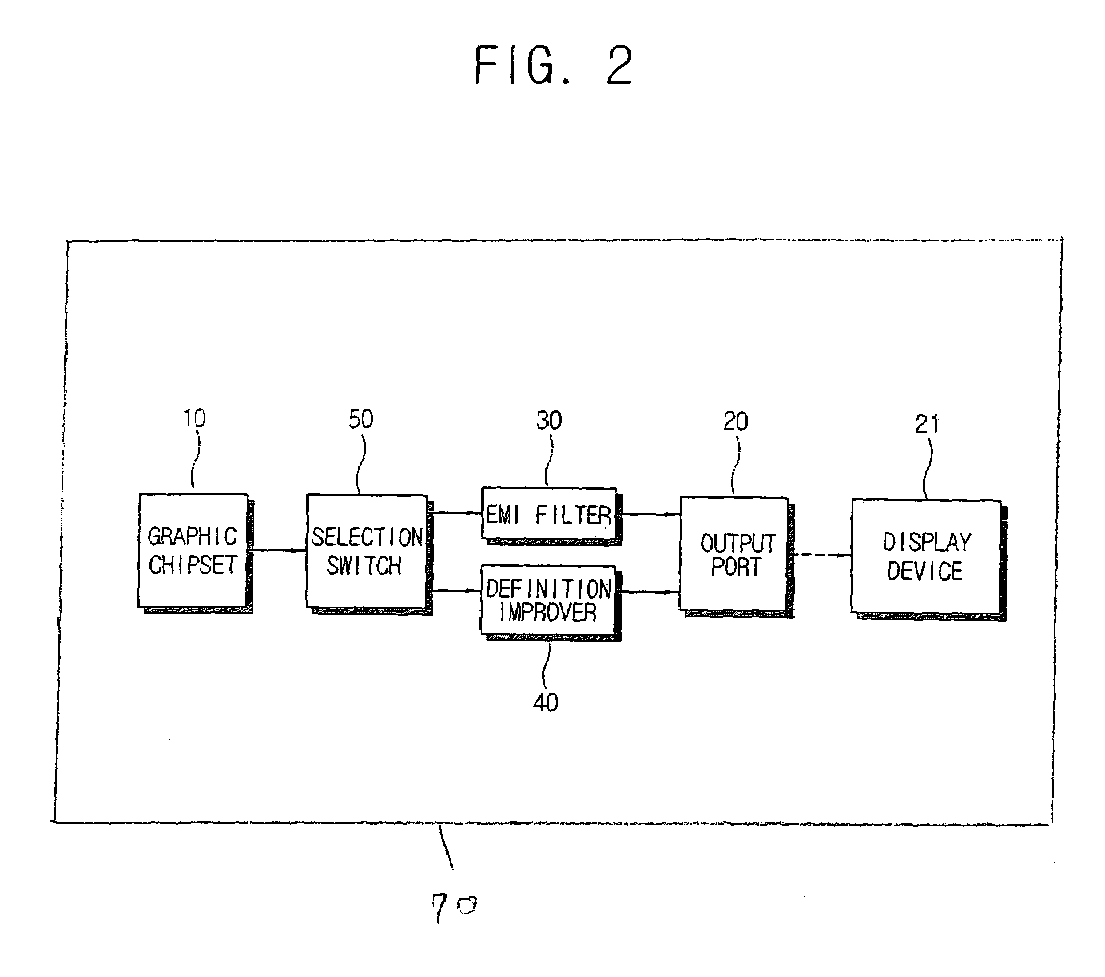
[0026]FIG. 2 is a block diagram of a computer system 70 according to an embodiment of the present invention.

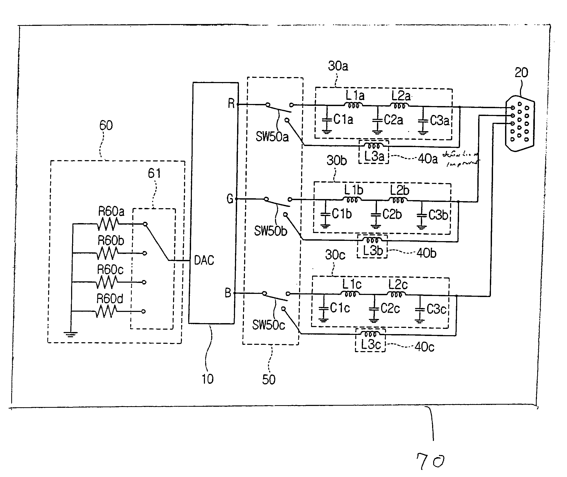
[0027]As shown in FIG. 2, a computer system 70 according to this embodiment of the present invention comprises a graphic chipset 10, an output port 20, a display device 21, an EMI filter 30, a definition improver 40, and a selection switch 50.

[0028]The graphic chipset 10 generates RGB signals, characterizing RGB components, and horizontal / vertical synchronizing signals. The graphic chipset 10 is generally provided in a graphic card, but may be mounted on a main board.

[0029]The output port 20 is used in transmitting a video signal, etc., generated in the graphic c...


PUM


Abstract

A computer system including a graphic chipset generating RGB signals characterizing RGB components, and an output port through which the RGB signals are transmitted from the graphic chipset to a display device, further including an EMI filter to filter EMI from the RGB signals generated by the graphic chipset, and to transmit the filtered RGB signals to the output port; a definition improver to adjust an output level of the RGB signals generated by the graphic chipset to a predetermined output level, and to transmit the adjusted RGB signal to the output port; and a selection switch to selectively connect an output terminal of the graphic chipset with the EMI filter or the definition improver.

Description

CROSS-REFERENCE TO RELATED APPLICATIONS[0001]This application claims the benefit of Korean Patent Application No. 2003-90650, filed Dec. 12, 2003, in the Korean Intellectual Property Office, the disclosure of which is incorporated herein by reference.BACKGROUND OF THE INVENTION[0002]1. Field of the Invention[0003]The present invention relates to a computer system, and, more particularly, to a computer system comprising a video interface outputting red, green and blue (RGB) signals after filtering electromagnetic interference (EMI).[0004]2. Description of the Related Art[0005]FIG. 1 is a schematic circuit diagram of a video interface in a conventional computer system.[0006]As shown therein, a video interface comprises a graphic chipset 100, a resistor R100, EMI filters 110a through 110c, and an output port 120.[0007]The graphic chipset 100 is employed as an auxiliary processor to process a video signal, and comprises a digital-to-analog converter (DAC) input terminal, and RGB output ...

Claims


Application Information

Patent Timeline
Patent Type & Authority Patents(United States)
IPC IPC(8): G09G5/02G06F3/14G06F3/153G09G5/00G09G5/04G09G5/36
CPCG09G5/006G06F3/14
Inventor HWANG, YONG-SANG
Owner SAMSUNG ELECTRONICS CO LTD
Learn More