Redistribution of parts in a distribution network

Active Publication Date: 2007-05-01
BLUE YONDER GRP INC
View PDF14 Cites 75 Cited by
  • Summary
  • Abstract
  • Description
  • Claims
  • Application Information

AI Technical Summary

Benefits of technology

[0004]In accordance with the present invention, disadvantages and problems associate

Problems solved by technology

As a result, maintaining an optimal inventory of parts at each location that best serves

Method used


Image

  • Redistribution of parts in a distribution network
  • Redistribution of parts in a distribution network
  • Redistribution of parts in a distribution network

Examples


Example

DETAILED DESCRIPTION OF THE DRAWINGS

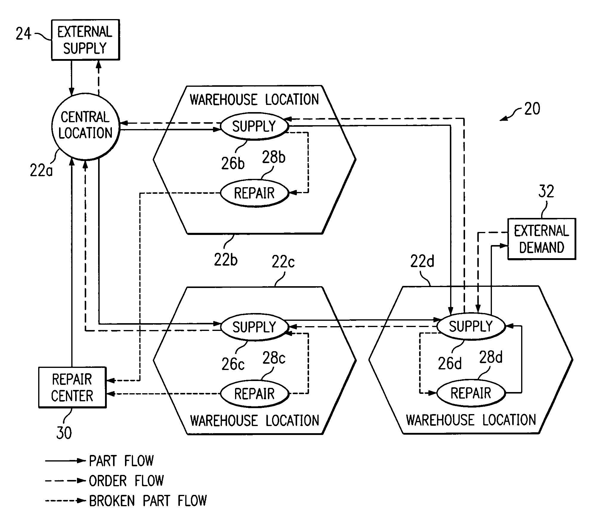
[0019]FIG. 1 illustrates an example distribution network 20 for deploying and redistributing inventory of one or more parts among one or more locations 22. Distribution network 20 includes locations 22 that distribute parts throughout distribution network 20. A part may comprise, for example, a product, a portion of a product, a device used to manufacture a product, or any other suitable item that may be distributed from one location 22 to another location 22 in distribution network 20.

[0020]In one embodiment, locations 22 include a central location 22a and one or more warehouse locations 22b–d. Although central location 22a and warehouse locations 22b–d are illustrated, distribution network 20 may include any suitable number of central locations 22 and warehouse locations 22. Each location 22 may comprise a supply location and / or a demand location. A supply location supplies a part to a demand location, and may supply the part in response to an o...


PUM


Abstract

Redistributing parts includes defining locations. An actual inventory of parts is established among the locations, and a desired allocation of the parts is established among the locations. A demand for the parts at each location is determined using the actual inventory and the desired allocation. Paths are determined, where a path transfers an excess part from one location to another location. A transfer function describing a cost of transferring the excess part along the paths is generated. The transfer function is optimized to achieve the desired allocation of the excess parts at a minimum cost.

Description

RELATED APPLICATIONS[0001]This application claims benefit under 35 U.S.C. § 119(e) of U.S. Provisional Application Ser. No. 60 / 243,659, filed Oct. 26, 2000, entitled “SYSTEM AND METHOD FOR OPTIMIZED DEPLOYMENT OF INVENTORY, OR RE-DISTRIBUTION OF EXISTING INVENTORY, ACROSS A MULTI-ECHELON DISTRIBUTION NETWORK.”TECHNICAL FIELD OF THE INVENTION[0002]This invention relates generally to the field of inventory distribution networks and more specifically to redistribution of parts in a distribution network.BACKGROUND OF THE INVENTION[0003]Distribution networks may include one or more locations that receive parts from a vendor and distribute the parts within the distribution network in order to provide a customer with a product. The parts may be, for example, manufactured into a product within the distribution network. Distribution networks may include locations that both supply parts to and receive parts from other locations. Performance at each location is thus affected by the performance...

Claims


Application Information

Patent Timeline
IPC IPC(8): G06Q30/00G06Q10/00
CPCG06Q10/00G06Q10/0631G06Q10/06312G06Q10/087G06Q10/0875
Inventor BIRJANDI, ROSA H.BAKKALBASI, OMERVEERAPPANAICKER, DHARMARAJSHAPIRO, JOEL A.
Owner BLUE YONDER GRP INC
Why Eureka
Try Eureka