Sleeved stop for a drill bit

a drill bit and sleeves technology, applied in the field of sleeves for drill bits, can solve the problems of inadequacies, difficulty in identifying the desired depth of a hole being drilled, and lack of suitable means for finely controlling the precise depth to which the drill bit may extend

Active Publication Date: 2007-05-01
3D SCAN GUIDE LLC
View PDF37 Cites 286 Cited by
  • Summary
  • Abstract
  • Description
  • Claims
  • Application Information

AI Technical Summary

Problems solved by technology

One common problem associated with the use of drills is that it may be difficult to identify the desired depth of a hole being drilled.
While this approach works satisfactorily in carpentry, it is not appropriate, for example, in oral surgery, where a more precise (and sanitary) form of stop is needed.
The stop, however, does not provide any means for finely controlling the precise depth to which the bit may extend.
The stop is threaded and may be set to the desired depth but it does not provide a means of fine adjustment, as the threads are widely spaced.
Alternatively, if the threads are finely spaced, coarse movements would be difficult, since many turns of the thread would be required to move the stop larger distances.
This suffers from the drawback that the adjustment of the depth of the hole to be drilled is limited by the distance between the grooves.

Method used


Image

  • Sleeved stop for a drill bit
  • Sleeved stop for a drill bit
  • Sleeved stop for a drill bit

Examples


Embodiment Construction

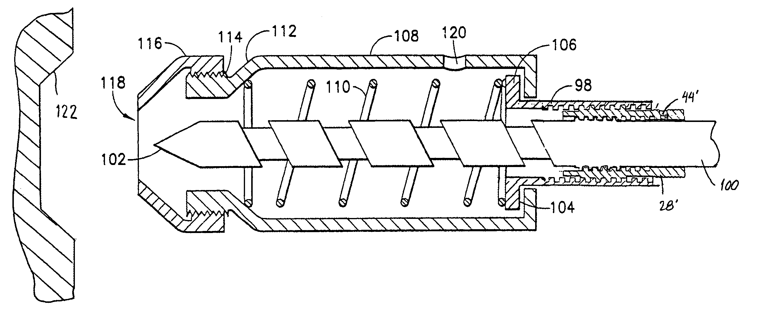
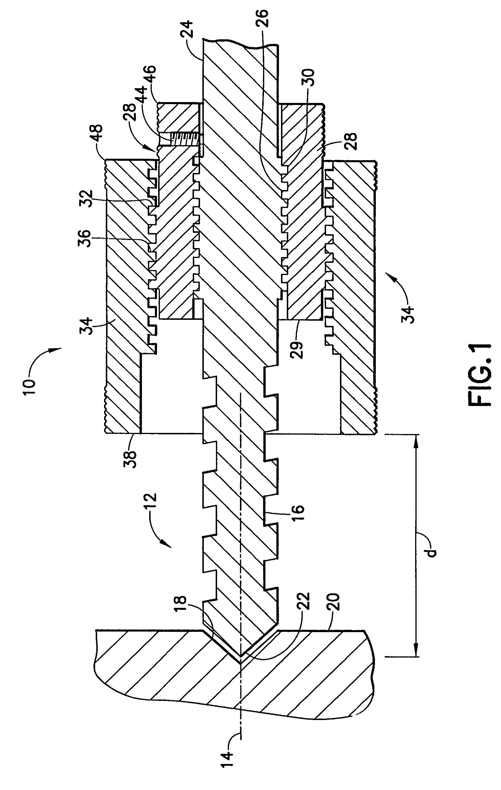
[0022]In FIG. 1 there is shown a stop 10 for a drill bit 12 in accordance with a preferred embodiment of the invention. Bit 12 is intended for use with a drill (not shown) which may be either electric or manual (such as, for example, an auger or gimlet). In accordance with standard practice, bit 12 is removably mounted in the drill for rotational movement about an axis 14 (shown in dashed line). Bit 12 includes a helical cutting groove 16 for drilling a hole 18 in a surface 20.

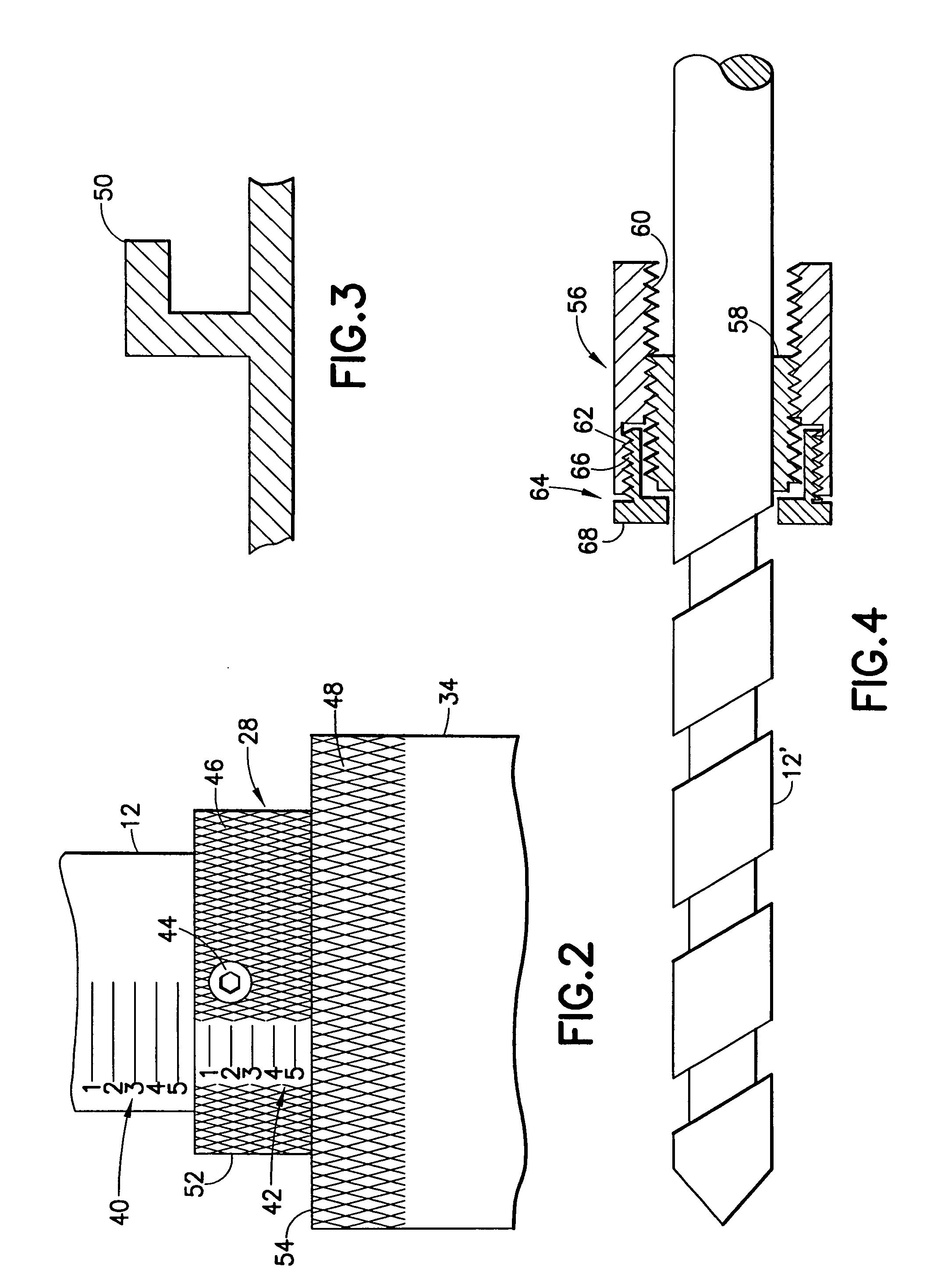
[0023]As is conventional, bit 12 includes a tip 22, and an opposed end 24. A threaded area 26 is provided between the tip 22 and end 24 on the exterior of bit 12. Stop 10 includes a first inner sleeve 28 engageable with bit 12, and rotatable about axis 14. Inner sleeve 28 includes an inner threaded area 30 and an outer threaded area 32. The inner threaded area has threading dimensioned to engage threaded area 26 of bit 12. Stop 10 further includes a second outer sleeve 34 which is engageable with inner sleeve ...


PUM

PropertyMeasurementUnit
resilientaaaaaaaaaa
depth of penetrationaaaaaaaaaa
diameteraaaaaaaaaa

Abstract

A stop for use with an electric drill bit, the stop having at least one threaded sleeve for positioning the stop relative to a surface into which the drill bit will extend. The stop may have both an inner and an outer sleeve. The sleeves are mounted coaxially, one inside the other about the drill bit. One of the sleeves, preferably the inner sleeve, provides coarse adjustment of the position of the shoulder relative to the tip of the bit, while the other, preferably the outer sleeve, provides fine adjustment of the position of the shoulder relative to the top of the bit.

Description

BACKGROUND OF THE INVENTION[0001]1. Field of the Invention[0002]This invention is directed to the field of hardware for use with drills, and, more particularly, to a sleeved stop for a drill bit.[0003]2. Description of Related Art[0004]Drills are common hand tools. They are used in many applications, from home repair to surgery. One common problem associated with the use of drills is that it may be difficult to identify the desired depth of a hole being drilled. In some applications, such as installing door hinges, attaching legs to a table, or during surgery (e.g., dental surgery, neurosurgery, orthopedic surgery, or maxillofacial surgery), drilling the hole to a precise depth is of crucial importance, and so precise control of the depth of penetration of the drill bit is essential.[0005]In simple applications, crude means have existed for providing a stop for the drill bit. In carpentry, for example, it is common to provide a visual stop for a drill bit by applying a long piece of...

Claims


Application Information

Patent Timeline
Patent Type & Authority Patents(United States)
IPC IPC(8): B23B51/02B23B39/00B23B41/00B23B45/14B23B47/00B23B49/00B23B51/00B23Q17/22
CPCA61B17/1615B23B49/005B23Q17/2233B23B51/0054A61B17/1617A61B2019/306A61C5/025Y10T408/558B23B2260/088Y10T408/99Y10T408/564Y10T408/8925A61B2090/036A61C5/44
Inventor GREENBERG, ALEX M.
Owner 3D SCAN GUIDE LLC
Why Eureka
Try Eureka