
Switch and disconnector apparatus for electric substations

a technology of electric substations and disconnectors, applied in the direction of air-break switch details, earpiece switches, switches with movable electrical contacts, etc., can solve the problems of deterioration of conductive materials, difficult to achieve, and inconvenient installation of apparatuses inside metal casings

Inactive Publication Date: 2007-05-01
AREVA T&D ITAL
View PDF26 Cites 10 Cited by
  • Summary
  • Abstract
  • Description
  • Claims
  • Application Information

AI Technical Summary

Benefits of technology

[0041]According to the present invention, two, three or more switch and disconnector apparatuses as described above are associated so as to form a two-phase, three-phase or multi-phase apparatus. In this case, the telescopic connecting rod of each individual switch and disconnector apparatuses is rotatable about a same axis of rotation.

Problems solved by technology

These apparatuses, however, are not suitable for installation in prefabricated installations inside a metal casing (switchboards formed by means of prefabricated cubicles) since in this case segregation between the two terminals, i.e. the upper and lower terminal of the apparatus, is required, at least when the switch and disconnector apparatus is in a open condition, so as to allow access to the cable bay of the cubicle with the live busbars.
This latter condition is difficult to achieve in the case of hinge-type switch and disconnector apparatuses.
This earthing disconnector is interlocked with the door providing access to the cubicle so that it is not possible to open said door if the earthing disconnector is not in the closed position.
For example, in environments which are polluted or have a severe climate there is a deterioration of the conductive materials, in particular the parts making sliding contact, until, with time, seizing of said parts occurs.
However, in the case of installations in humid and / or polluting climates, this is not possible with the known linear air switch and disconnector apparatuses unless they are subject to frequent programmed maintenance.
On the other hand, the present tendency, primarily for cost-related reasons, is that of keeping the maintenance carried out on apparatus to a minimum.
Another drawback precisely of linear air switch and disconnector apparatuses is that they must be mounted on a particularly strong metal structure which is able to withstand, without deformation, considerable forces so as to operate the arm which moves axially the bar or tube of conductive material.
Therefore, in known switch and disconnector apparatuses there is the risk that an arc may occur between phases and that an (otherwise harmless) “non interruption” may result in a two-phase or three-phase short-circuit.
This does not eliminate entirely the abovementioned problems and in any case results in the apparatus being excessively voluminous.

Method used


Image

  • Switch and disconnector apparatus for electric substations
  • Switch and disconnector apparatus for electric substations
  • Switch and disconnector apparatus for electric substations

Examples


Embodiment Construction

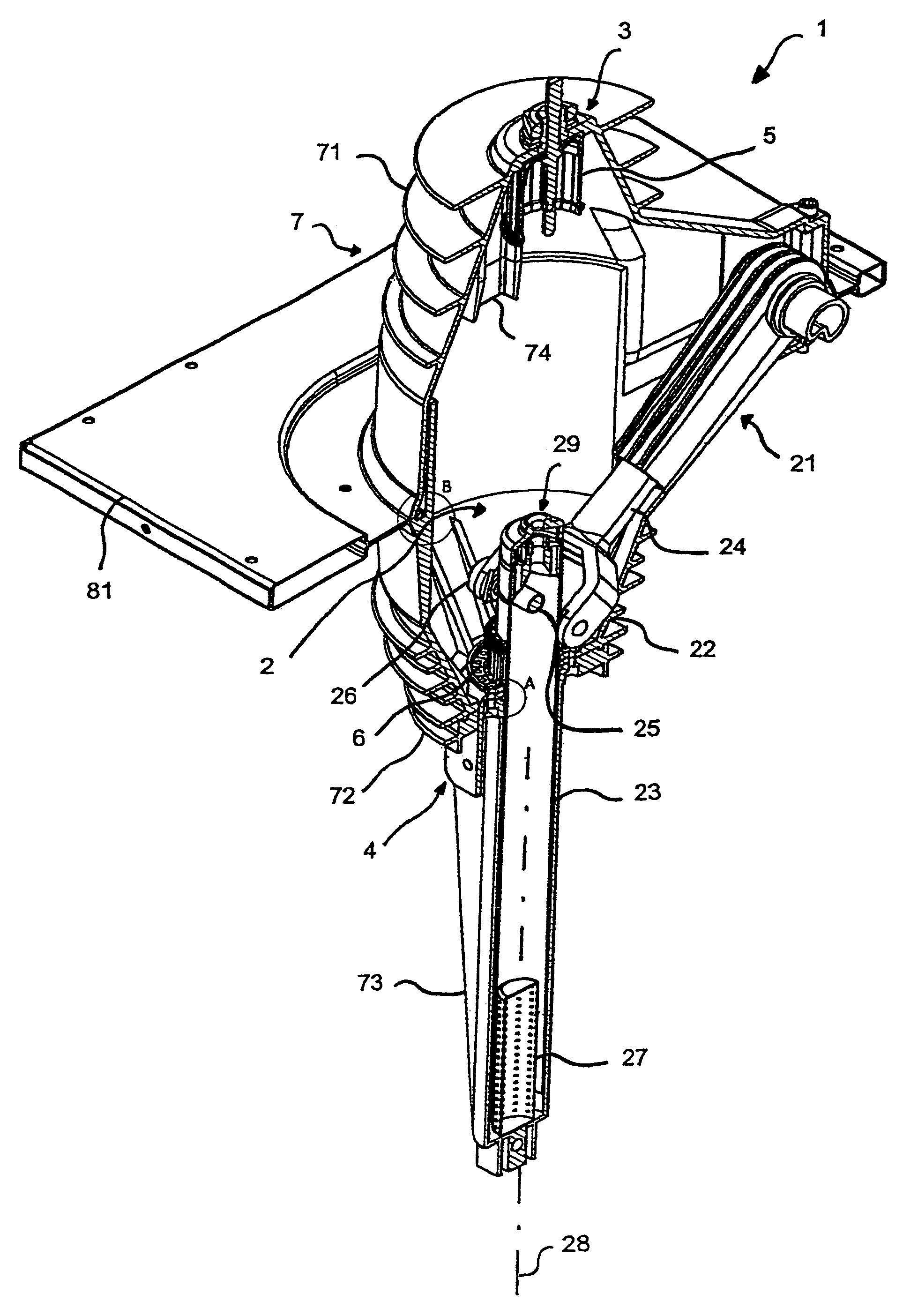
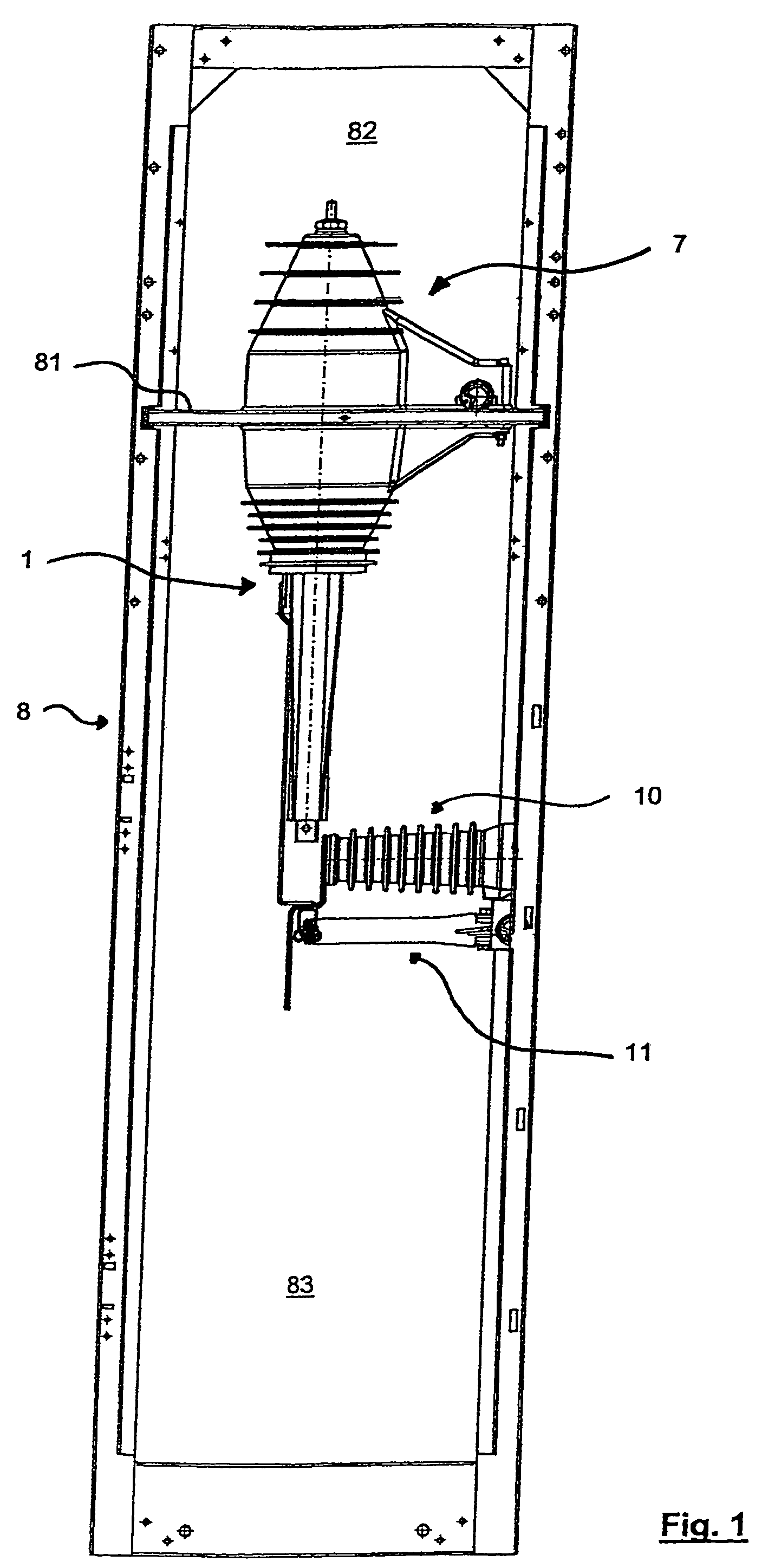
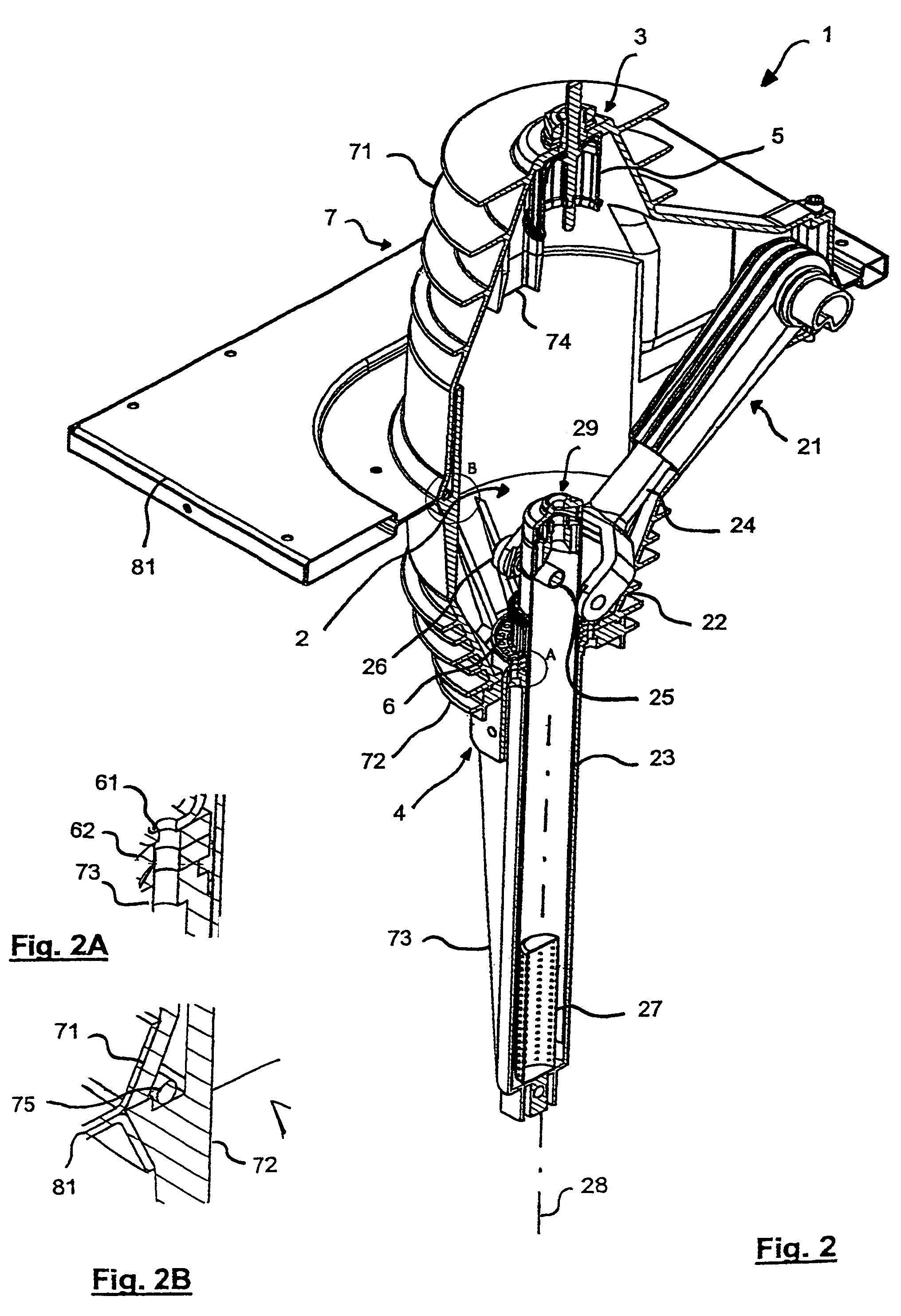
[0053]With reference to FIGS. 1–4, the linear air switch and disconnector apparatus according to the invention is indicated overall by the reference number 1. Two, three or more switch and disconnector apparatuses 1 may be associated together so as to obtain a switch and disconnector apparatus which is two-phase, three-phase, etc. FIG. 1 shows the switch and disconnector apparatus 1 according to the invention inside a cubicle 8 supported by a base 81. FIG. 1 also shows a capacitive insulator 10 and an earthing disconnector 11. The capacitive insulator 10 is an insulator which, in addition to the usual function of keeping supported and isolated busbars which are normally live, also has the function of detecting the voltage. This function is performed by means of a capacitive coupling (a capacitor) situated inside the said insulator which enables a signal to be obtained or otherwise, depending on whether or not there is voltage on the busbar.

[0054]The earthing disconnector 11 is a saf...


PUM


Abstract

A switch disconnector apparatus of the linear air type is described, said apparatus comprising: an upper device for transferring current, a fixed upper contact connected electrically to the upper device, a lower device for transferring current, a sliding lower contact connected electrically to the lower device and a contact tube movable between a closing position and a disconnecting position. According to the invention, the apparatus also comprises a casing of insulating material which forms a protective atmosphere. Moreover, the contact tube, the upper contact and the lower contact are substantially completely enclosed inside the casing. The disconnector is therefore closed, inside a protected environment, segregated, but not perfectly sealed. With the present invention all the drawbacks associated with unprotected air systems are avoided and a compact and safe apparatus preventing discharges between several phases is provided.

Description

[0001]This application is based on application No. MI2004A 0001708 filed in Italy, the content of which is incorporated hereinto by reference.BACKGROUND[0002]1. Field of the Invention[0003]The present invention relates to an electrical apparatus suitable for installation in prefabricated installations inside a metal or insulating casing, which form medium-voltage switchboards. In particular, it relates to an apparatus which, in the closed position, is able to convey in a controlled manner, in keeping within the limits set forth in relevant regulations, the rated current required by the load to which the apparatus is connected and withstand the short-circuit current which may arise as a result of a fault at its terminals. The apparatus according to the invention is able to establish, in its open position, the short-circuit current due to a fault at its terminals. Finally, in the open position, it is able to ensure a disconnecting level suitable for the voltage level of the installati...

Claims


Application Information

Patent Timeline
Patent Type & Authority Patents(United States)
IPC IPC(8): H01H33/14H01H31/02H01H31/32H01H33/12H01H33/91
CPCH01H1/38H01H31/003H01H31/02H01H31/32H01H33/121H01H33/91
Inventor VAGHINI, ALBERTOROSSI, ARMANDOPERLI, GIORGIO
Owner AREVA T&D ITAL
Learn More