Antenna device and portable radio terminal

a portable radio terminal and antenna device technology, applied in the field of antennas, can solve the problems of inability to have uniform field emission pattern characteristics, and inability to further miniaturize them from the operational point, and achieve good antenna characteristic regardless of direction

Inactive Publication Date: 2007-05-08
LENOVO INNOVATIONS LTD HONG KONG
View PDF10 Cites 95 Cited by
  • Summary
  • Abstract
  • Description
  • Claims
  • Application Information

AI Technical Summary

Problems solved by technology

While a portable radio terminal is getting smaller and smaller, it has limitations for further miniaturization thereof from the operational point of view.
Therefore, as represented by a half wave dipole antenna, it is not possible to have the uniform field emission pattern characteristic in a horizontal surface, and an abrupt drop (null point) appears in the horizontal surface.
Thus, the field emission pattern characteristic does not become uniform because of the current of the housing, and an abrupt drop (null point) arises in the horizontal surface.
There has been the problem that it is not possible for a portable radio terminal to stably receive radio signals if the housing thereof has such a field emission characteristic and the reception characteristic changes depending on the direction of the terminal.
Therefore, when the art is applied to an antenna in a portable radio terminal, radio signals cannot be transmitted and received between a radio terminal and another radio terminal or a base station depending on the aspect of the radio terminal.
Also, the second prior art is so-called antenna array having a plurality of antennas, and therefore, it is difficult to apply the art to a portable radio terminal being required to be made smaller and lighter.
As above, it has not been provided an antenna device capable of being applied to a portable radio terminal and also showing a good radiation characteristic regardless of the direction of the terminal.

Method used


Image

  • Antenna device and portable radio terminal
  • Antenna device and portable radio terminal
  • Antenna device and portable radio terminal

Examples


first embodiment

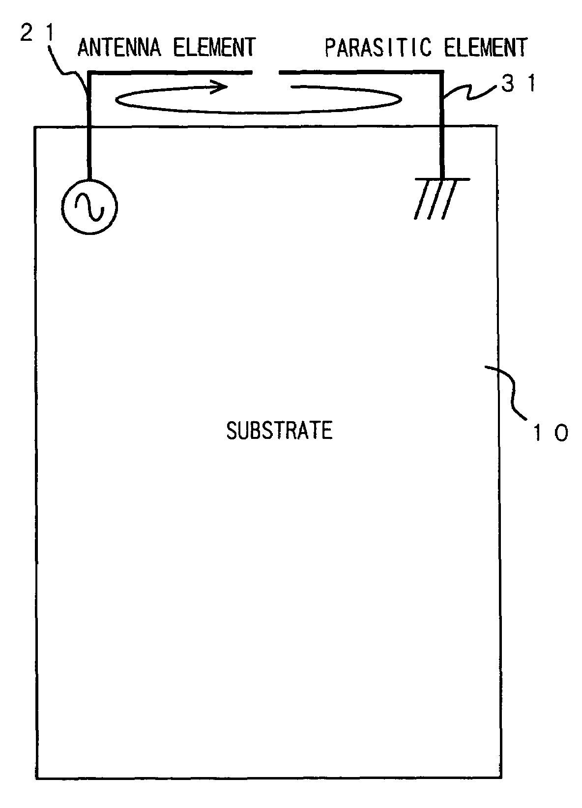
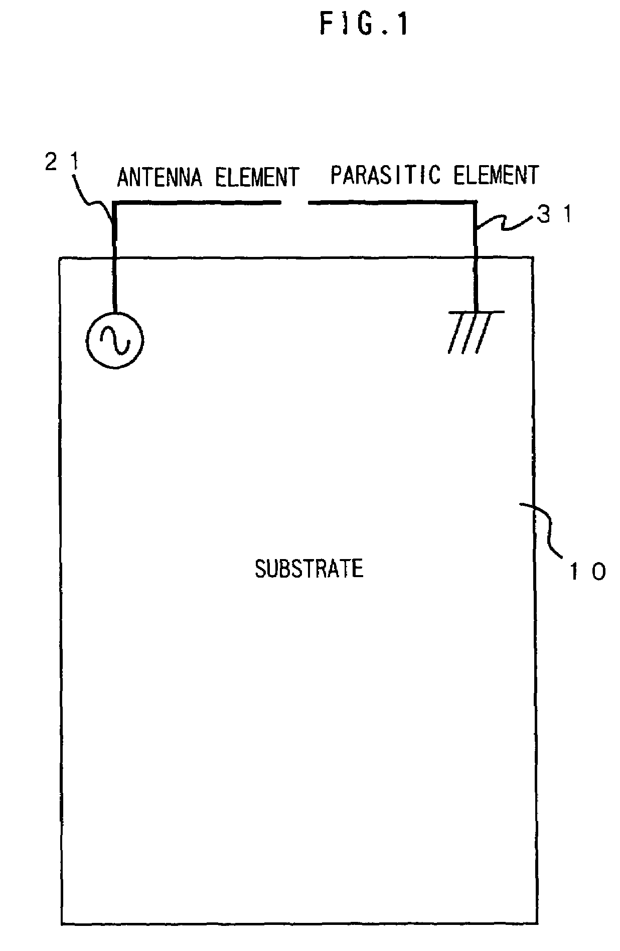
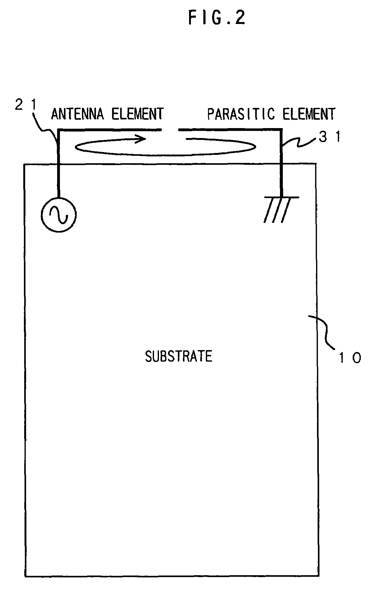
[0078]A description will be given of the present invention. FIG. 1 is a diagram showing the structure of an antenna device according to this embodiment and FIG. 2 is a diagram showing the operation of the antenna device according to this embodiment. In the antenna device, an antenna element 21 and a parasitic element 31 are attached on one end of a substrate 10. At least one point of one end of the antenna element 21 is electrically connected to a signal wiring pattern on the substrate 10 and the other end of the antenna element is an open end. One end of the parasitic element 31 is connected to the ground of the substrate 10 and the other end of the parasitic element 31 is an open end.

[0079]The antenna element 21 and the parasitic element 31 are substantially L-shaped or reverse L-shaped and both of the open ends are disposed in proximity to each other and their fore-ends are in alignment.

[0080]When the open ends of the antenna element 21 and the parasitic element 31 are disposed a...

second embodiment

[0088]A description will be given of the present invention. FIG. 6 is a diagram showing an antenna device of this embodiment. In the antenna device, the antenna element 22 and the parasitic element 32 are attached on one end of the substrate 10. The antenna element 22 is electrically connected to a signal wiring pattern on the substrate 10 at least at one point of one end and also to a ground pattern, and the other end of the antenna element 22 is an open end. One end of the parasitic element 32 is connected to the ground of the substrate 10 and the other end of the parasitic element 32 is an open end.

[0089]The antenna element 22 is substantially F-shaped or reverse F-shaped and the parasitic element 32 is substantially L-shaped or reverse L-shaped, and both ends are disposed in proximity in alignment.

[0090]When the open ends of the antenna element 22 and the parasitic element 32 are disposed as above, as is the case with the antenna device of the first embodiment, high-frequency lo...

third embodiment

[0092]A description will be given of the present invention. FIG. 7 is a diagram showing an antenna device of this embodiment. In the antenna device, the antenna element 23 and the parasitic element 33 are attached on one end of the substrate 10. At least one point of one end of the antenna element 23 is electrically connected to a signal wiring pattern on the substrate 10 and the other end of the antenna element 23 is an open end. One end of the parasitic element 33 is connected to the ground of the substrate 10 and the other end of the parasitic element 33 is an open end.

[0093]The antenna element 23 is substantially L-shaped or reverse L-shaped and the parasitic element 33 is substantially I-shaped, and both of the open ends are disposed in proximity.

[0094]When the open ends of the antenna element 23 and the parasitic element 33 are disposed as above, as is the case with the antenna device of the first embodiment, high-frequency loop current passes through the ground of the substra...


PUM


Abstract

An antenna device capable of being applied to a portable radio terminal and showing a good antenna characteristic regardless of the direction, and a portable radio terminal provided with the antenna device. The antenna device applied to a portable radio terminal whose housing length is equal to or more than λ / 4 with respect to the wavelength λ of transmission-reception signals comprises an antenna element disposed on one end of the housing in the longitudinal direction in which at least one point of one end is connected to a signal wiring pattern on a substrate and the other end is an open end, and a parasitic element disposed on the same side of the housing as the antenna element in which one point of one end is connected to a ground wiring on the substrate and the other end is an open end, wherein the open end of the antenna element and the open end of the parasitic element are approximated to each other and capacity coupled.

Description

BACKGROUND OF THE INVENTION[0001]1. Field of the Invention[0002]The present invention relates to an antenna device incorporated in a small-sized radio terminal, especially to an antenna device showing a good reception characteristic for high-frequency radio signals regardless of direction and a portable radio terminal provided with the antenna.[0003]2. Description of the Prior Art[0004]In recent years, a portable radio terminal typified by a mobile phone often uses radio signals in a high-frequency band. For instance, the frequency used in the third generation mobile phone goes beyond 2 GHz (gigahertz), and has a tendency to shift to the higher frequencies.[0005]While a portable radio terminal is getting smaller and smaller, it has limitations for further miniaturization thereof from the operational point of view. Accordingly, as the higher frequencies are used, the length of a housing of a portable radio terminal often becomes beyond more than half of the wavelength λ, being λ / 2.[0...

Claims


Application Information

Patent Timeline
Patent Type & Authority Patents(United States)
IPC IPC(8): H01Q1/24H01Q1/36H01Q1/38H01Q5/00H01Q9/42H01Q11/08
CPCH01Q1/243H01Q5/371H01Q9/42H01Q1/36
Inventor HARANO, NOBUYA
Owner LENOVO INNOVATIONS LTD HONG KONG
Why Eureka
Try Eureka