Precision printed circuit board based rogowski coil and method for manufacturing same

a printed circuit board and coil technology, applied in the field of rogowski coils, can solve the problems of significant reduction of coil densities, and patent failure to provide adequate means for external field cancellation

Inactive Publication Date: 2007-06-05
SCHWEITZER ENGINEERING LABORATORIES
View PDF49 Cites 63 Cited by
  • Summary
  • Abstract
  • Description
  • Claims
  • Application Information

AI Technical Summary

Problems solved by technology

The patent fails to provide adequate means for external field cancellation due to inadequate handling of the coil return path.
While high sensitivity is very desirable when measuring low frequency currents (50 / 60 Hz power system related), the patent fails to provide adequate means for external field cancellation.
This problem is reported in U.S. Pat. No. 6,624,624 and is caused by inadequate handling of the coil return path.
A similar problem applies to the design reported in U.S. Pat. No. 6,313,623 (by Kojovic, et al.) in which two closely spaced coils with counter rotation are used to perform partial return path compensation.
Attempts to provide improved return path cancellation described in this patent results in significantly reduced coil densities, making the design less appropriate for low frequency (at about 50 / 60 Hz) current measurement applications.
In addition, although improved, all reported geometries suffer from Z-axis (board thickness) related sensitivity effects with an error path normally offset in the direction of the Z-axis (board thickness).

Method used


Image

  • Precision printed circuit board based rogowski coil and method for manufacturing same
  • Precision printed circuit board based rogowski coil and method for manufacturing same
  • Precision printed circuit board based rogowski coil and method for manufacturing same

Examples


Embodiment Construction

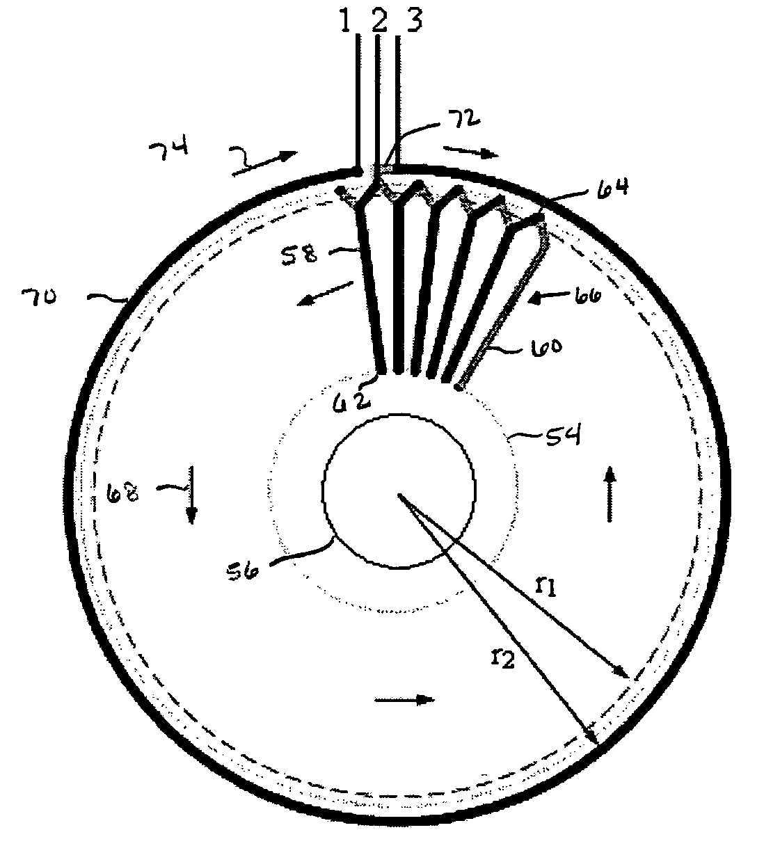
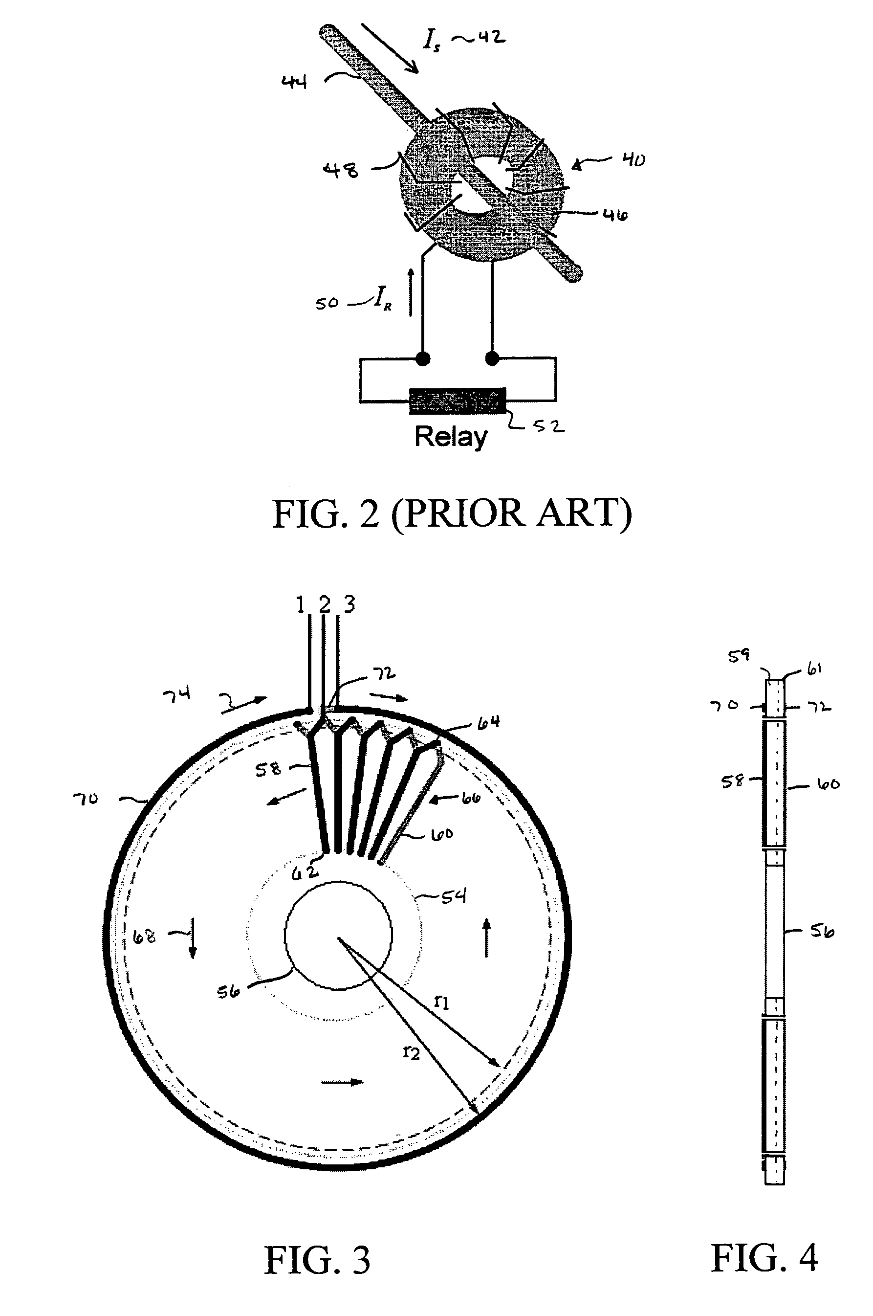
[0023]The multiple embodiments of this invention relate to a precision printed circuit board based Rogowski coil. This present invention printed circuit board based Rogowski coil may be used to measure magnetic fields and electrical currents. In one example of measuring electrical currents, the multiple embodiments may be used to enable low-voltage devices, such as power system control or protective devices, to measure and handle large currents flowing in a high-voltage power system.

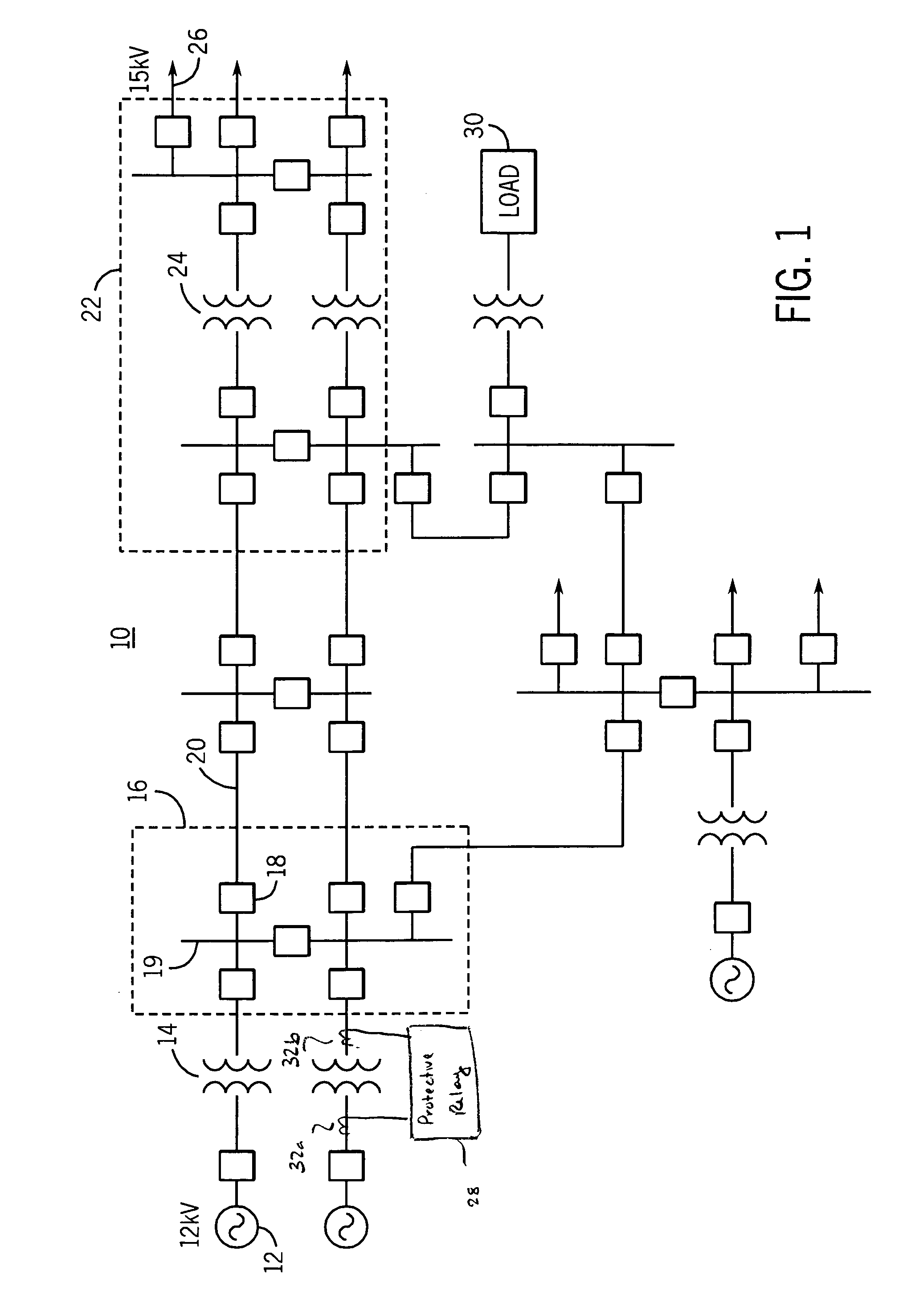
[0024]Generally, power system control or protective devices are used for protecting, monitoring, controlling, metering and / or automating electric power systems and associated transmission lines. These power system control or protective devices may include protective relays, RTUs, PLCs, bay controllers, SCADA systems, general computer systems, meters, and any other comparable devices used for protecting, monitoring, controlling, metering and / or automating electric power systems and their associated transm...


PUM

PropertyMeasurementUnit
temperatureaaaaaaaaaa
voltageaaaaaaaaaa
voltageaaaaaaaaaa

Abstract

A precision printed circuit board based Rogowski coil is formed including a printed circuit board including a first layer and second layer. The printed circuit board further defines an aperture for receiving an electrical path therethough. A first return path is defined about the aperture on the first layer of the printed circuit board, and a second return path—parallel to the first return path—is defined about the aperture on the second layer of the printed circuit board. A plurality of radial paths defined on the first layer of printed circuit board extend between the aperture and the first return path. A plurality of radial paths defined on the second layer of the printed circuit board extend between the aperture and the second return path. Each first layer radial path is connected with an adjacent second layer radial path to form a generally toroidally-shaped winding.

Description

BACKGROUND OF THE INVENTION[0001]The present invention concerns Rogowski coils. More particularly, the present invention concerns a printed circuit board based Rogowski coil and manner of making the same.[0002]Rogowski coils are electrical devices which measure of magnetic fields and electrical currents. They have been researched over the past century and are well known to the scientific literature. Their origin traces to the invention circa 1912 of the Rogowski coil by W. Rogowski and W. Steinhousen. The device is useful for measuring electrical currents and operates on the basis of a magnetic field integration performed across a closed contour being equal to the current flowing through the contour. The coil provides a voltage output proportional to the time derivative of the current (di / dt), rather than a current output like other traditional current transformers (e.g., the iron core current transformer of FIG. 2).[0003]Rogowski coils are popular because of their dynamic range and...

Claims


Application Information

Patent Timeline
Patent Type & Authority Patents(United States)
IPC IPC(8): H01F27/28
CPCG01R15/181H01F5/003
Inventor SKENDZIC, VESELIN
Owner SCHWEITZER ENGINEERING LABORATORIES
Why Eureka
Try Eureka