

Illumination device for simulating neon or similar lighting in the shape of a toroid
a technology of illumination device and toroid, which is applied in the direction of spectral modifier, gas-filled discharge tube, globe, etc., can solve the problems of inconvenient initial handling, installation and/or replacement, and the cost of neon lighting package and ship, and achieves the effects of low commercial or practical value of illumination devi
- Summary
- Abstract
- Description
- Claims
- Application Information
AI Technical Summary
Problems solved by technology
Method used
Image

Examples
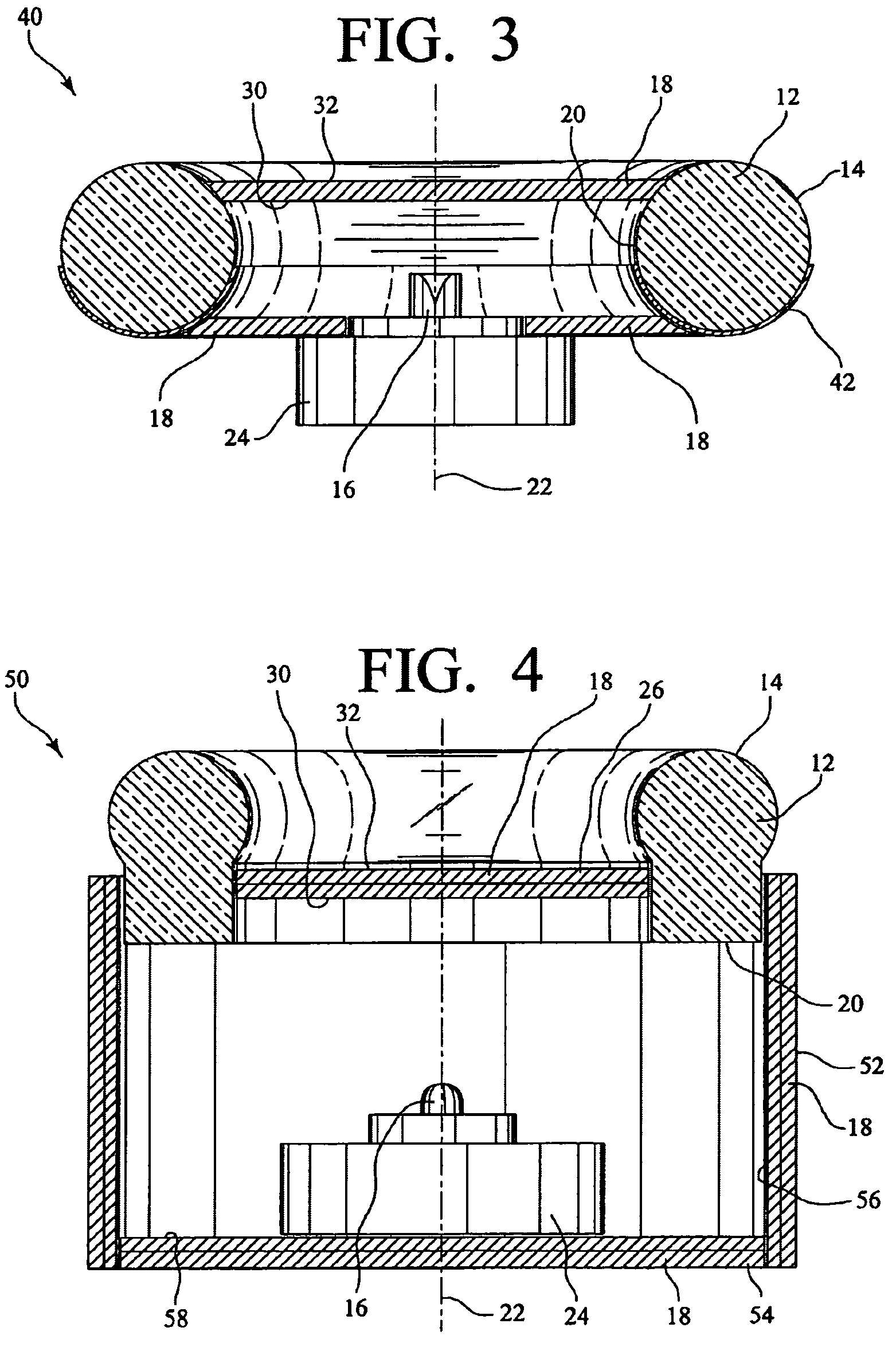
embodiment 40
[0031]FIG. 3 shows an alternate embodiment 40 of an illumination device for simulating neon or similar lighting in the shape of a toroid. Similar to previously described example, the illumination device 40 has a light-transmitting member 12, a light source 16, and a light-directing housing 18. However, the alternate embodiment of FIG. 3 also includes reflective tape 42 positioned around a lower portion of the light-transmitting member 12. Additionally, the light source 16 shown is a side-emitting LED, although for all of the embodiments described herein, top-emitting, or batwing, and side-emitting LEDs can be utilized.
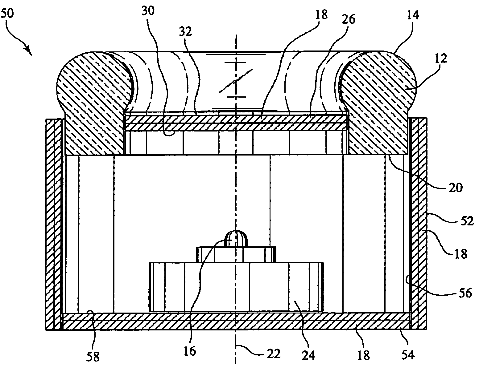
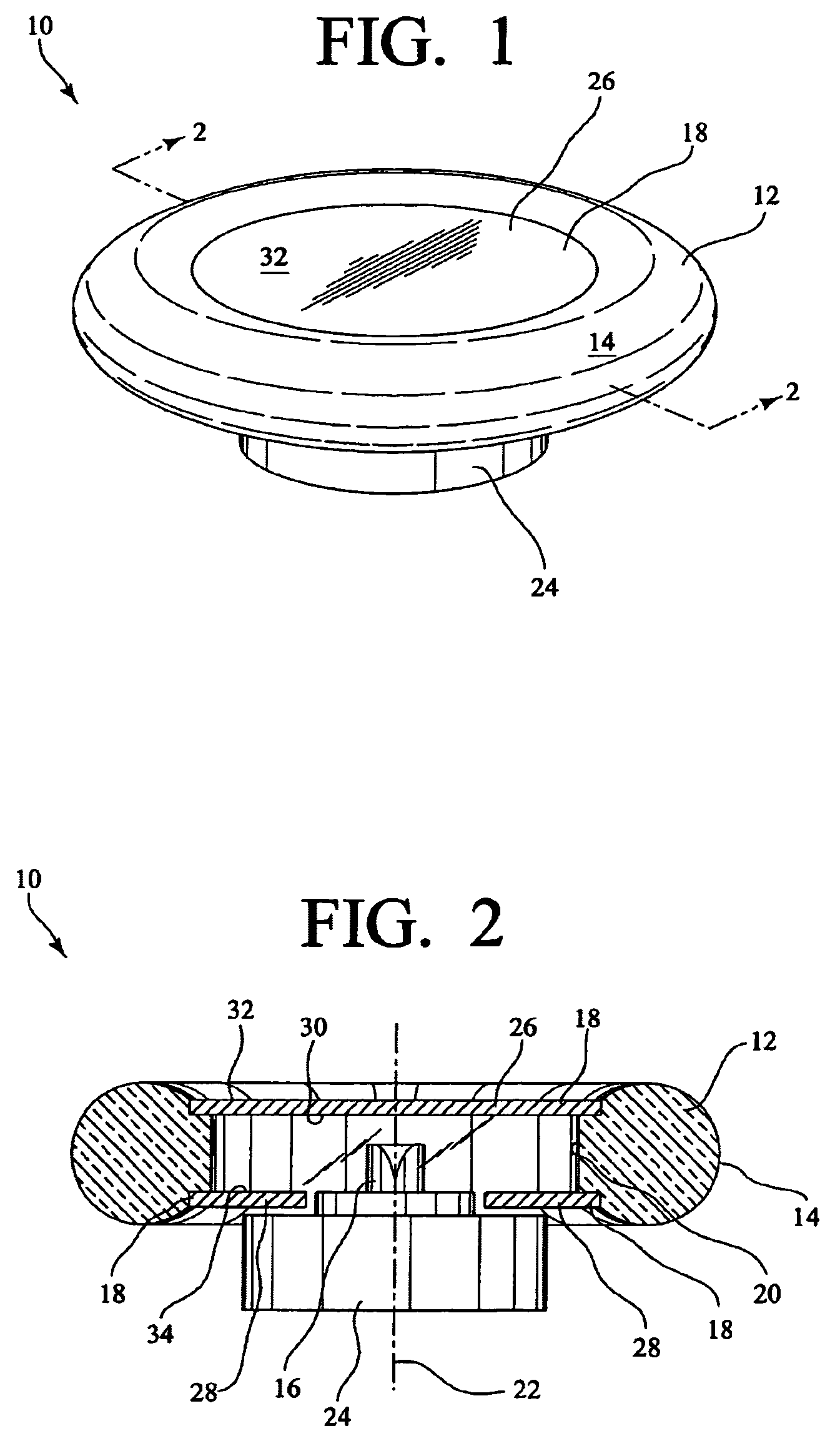
embodiment 50
[0032]FIG. 4 shows yet another alternate embodiment 50 of an illumination device for simulating neon or similar lighting in the shape of a toroid, having a light-transmitting member 12, a light source 16, and a light-directing housing 18. In this embodiment 50, the light source 16 is a top-emitting LED positioned along the central axis 22 of the toroidal light-transmitting member 12. However, the light source 16 is spaced a distance from the opening defined by the toroidal light-transmitting member 12. The light-directing housing 18 has a disk-shaped top reflector member 26, which has a substantially reflective interior surface 30 and a substantially non-reflective and / or absorbing outer surface 32. The light-directing housing 18 also has a bottom reflector member 28, which includes a cylindrical side wall 52 and a disk-shaped bottom wall 54. The side wall 52 has a substantially reflective interior surface 56, and the bottom wall 54 also has a substantially reflective interior surfa...
embodiment 80
[0036]FIG. 8 is a side sectional view of the embodiment 80 of FIG. 7, wherein it is demonstrated that light from the light source 16 (shown as a side-emitting LED) is directed into a light-receiving surface 20 of the light-transmitting member by a top reflector member 26 and a bottom reflector member 28. The bottom reflector member 28 and the outer reflector member 82 serve to limit the surface area of the light-transmitting member 12 that act as a light-emitting surface 14. However, in use, the light emitted has a substantially uniform intensity and brightness along the light-emitting surface 14 for simulating neon or similar lighting.
PUM
 Abstract
Description
Claims
Application Information