Eureka AIR delivers breakthrough ideas for toughest innovation challenges, trusted by R&D personnel around the world.

Linear solid-state lighting with a double safety mechanism free of shock hazard

a safety mechanism and linear technology, applied in the direction of lighting and heating apparatus, lighting support devices, coupling device connections, etc., can solve the problems of substantial current flow, shock risk, and the kind of led lamps always failing a safety tes

Active Publication Date: 2012-12-04
ALEDDRA INC
View PDF5 Cites 77 Cited by
  • Summary
  • Abstract
  • Description
  • Claims
  • Application Information

AI Technical Summary

Benefits of technology

[0014]The present invention uses a double safety mechanism in an LL lamp to fully protect the person from possible electric shock during re-lamping or maintenance.
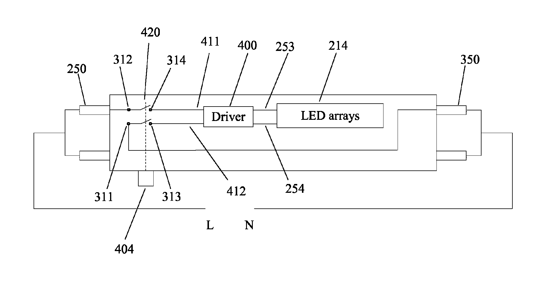
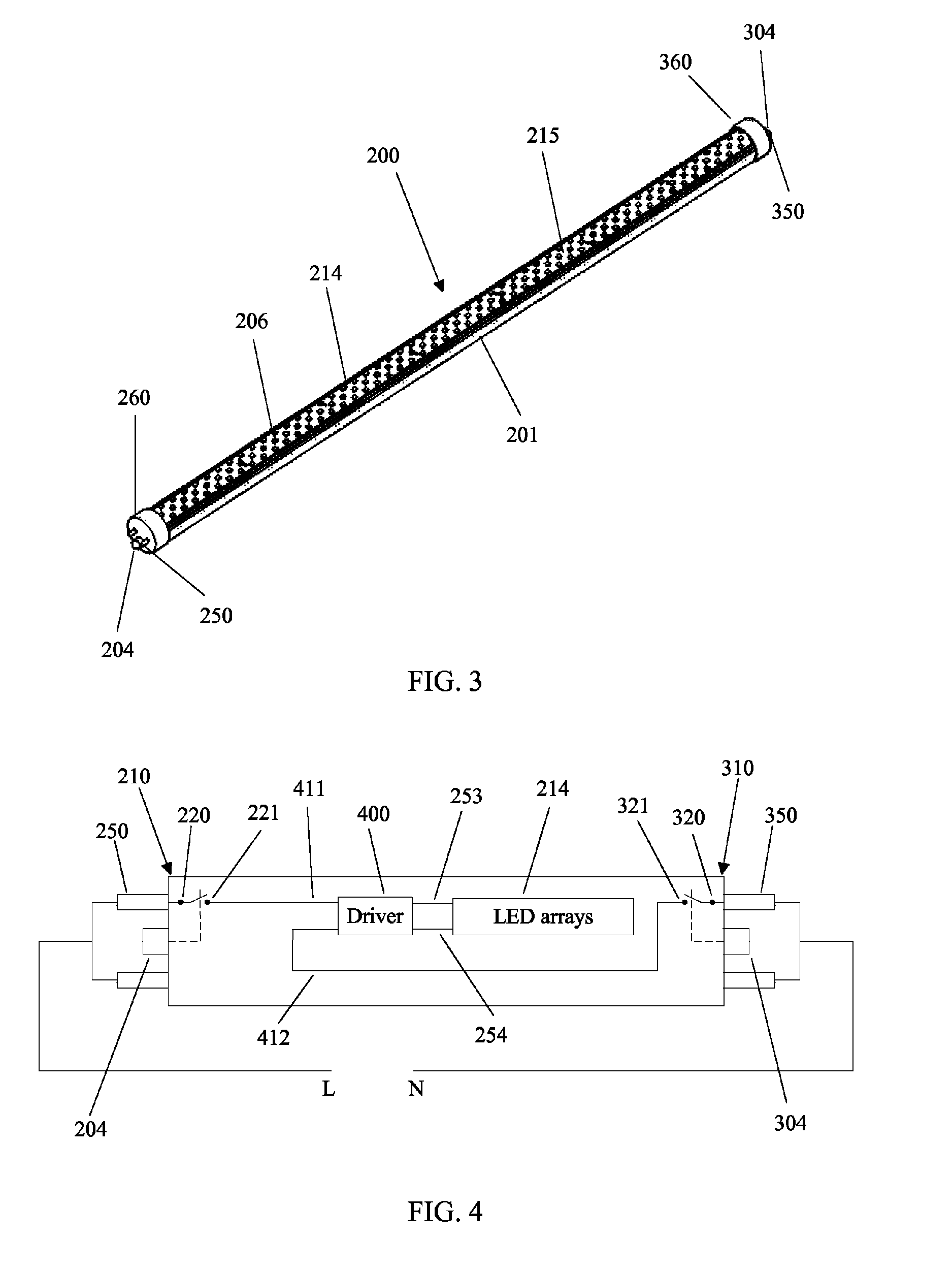
[0015]A linear light-emitting diode (LED)-based solid-state lamp comprising a heat sink, an LED driver, an LED printed circuit board (PCB) with a plurality of LEDs, a lens, and the double safety mechanism, is used to replace a fluorescent tube in an existing lamp fixture. The double safety mechanism comprises three shock protection switches: one each at two ends of the LL lamp and one preferably on the lateral side of the lamp. The shock protection switches at the two ends (“end shock protection switch” hereafter) are used to automatically shut off the internal electrical connections in the lamp when either one of bi-pins at the ends is out of the lamp socket. The third shock protection switch (“utility shock protection switch” hereafter) preferably on the side of the lamp is used to switch the connections on or off between both the line and neutral of the AC main and the two inputs of the LED driver at the same time. In such a scheme, no line voltage or accidental voltage spikes will possibly appear between the activated and the exposed bi-pins and between any of the bi-pins and the metallic heat sink during re-lamping or maintenance. Thus, any leakage current that may cause shock hazard is completely eliminated.

Problems solved by technology

This kind of LL lamps always fails a safety test, which measures through lamp leakage current.
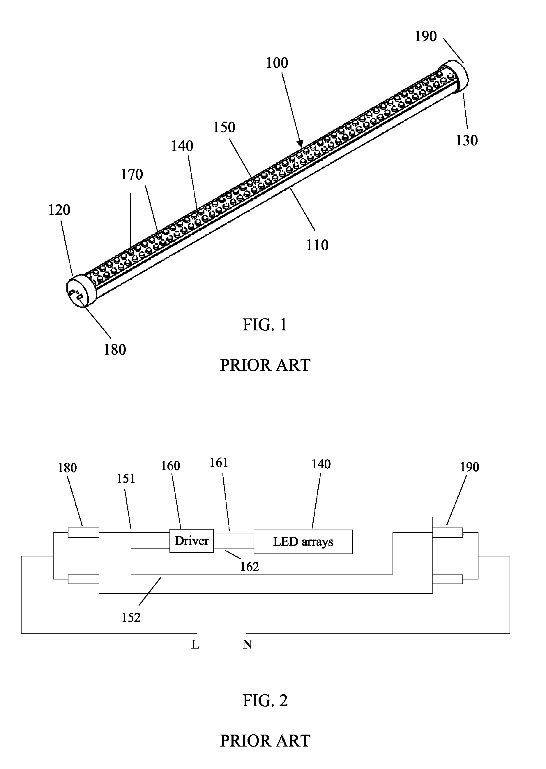
Because the line and the neutral of the AC main apply to both opposite ends of the tube when connected, the measurement of current leakage from one end to the other consistently results in a substantial current flow, which may present risk of shock during re-lamping.
One of the most important factors that detrimentally affect operating life of an LED-based lamp is high junction temperature of LEDs.
One of the drawbacks of using a metal as a heat sink in LL lamp application is electrical conductivity because shock hazard may occur when consumers touch the heat sink that is not well insulated from the LED printed circuit board (PCB) and the internal driver that powers the LEDs.
Not like LL lamps with an external driver that is inherently electric-shock free if the driver meets the dielectric withstand standard used in the industry, LL lamps with an internal driver and a metallic heat sink present another shock hazard during relamping or maintenance, when a substantial leakage current flows from any one of AC voltage input through the metallic heat sink to the earth ground.
When design flaws or material and workmanship defects appear, the electrical insulation in the LL lamp can break down, resulting in substantial leakage current flow.
When an LL lamp is operated under normal conditions, environmental factors such as dirt, contaminants, humidity, vibration, and mechanical shock can weaken the insulation and facilitate the current to flow through these small gaps and create a shock hazard to anyone who comes into contact with the metallic heat sink on the faulty LL lamps if care is not well taken.
Any products with electric shock hazards and risk of injuries or deaths are absolutely not acceptable for consumers.
However, commercially available LL lamps with internal drivers and a metallic sink, which are used to replace fluorescent tubes, fail to provide a solution to these problems.

Method used


Image

  • Linear solid-state lighting with a double safety mechanism free of shock hazard
  • Linear solid-state lighting with a double safety mechanism free of shock hazard
  • Linear solid-state lighting with a double safety mechanism free of shock hazard

Examples


Embodiment Construction

[0025]When an LL lamp is used as a lighting source, consumers used to use a power switch on the wall to turn the LL lamp power on or off. Intuitively, they just turn the LL lamp power off during relamping and maintenance and presume that it is safe, without any shock hazards. But somehow, if the wiring is such that the neutral wire goes to the switch while the hot wire is connected all the time to the LL lamp fixture, then there exists shock hazards during relamping and maintenance because the consumers may touch the exposed bi-pin when the other bi-pin is still in the electric lamp socket. One of the solutions is to use two end shock protection switches, one each on the two ends, such that the leakage current is blocked when either one of bi-pins is out of the lamp socket.

[0026]FIG. 3 is an illustration of an LL lamp with two end shock protection switches at both ends according to the present invention. The LL lamp 200 has a housing 201, two lamp bases 260 and 360, one at each end ...


PUM


Abstract

A linear light-emitting diode (LED)-based solid-state lamp having a double safety mechanism that comprises at least three shock protection switches, fully protects a person from possible electric shock during re-lamping or maintenance. One protection switch provided at each end of the lamp is able to cut off power when the associated end of the lamp is not inserted into the lamp socket. A third protection switch can be used to turn off the power from the AC main for additional shock protection.

Description

CROSS-REFERENCE TO RELATED APPLICATIONS[0001]This application is a continuation-in-part of U.S. patent application Ser. No. 12 / 645,390, filed Dec. 22, 2009, now pending. The prior application is incorporated herein by reference in its entirety.BACKGROUND OF THE INVENTION[0002]1. Field of the Invention[0003]This invention relates to linear light-emitting diode (LED) lamps and more particularly to a shock hazard-free linear LED lamp with a double safety mechanism.[0004]2. Description of the Related Art[0005]Solid-state lighting from semiconductor light-emitting diodes (LEDs) has received much attention in general lighting applications today. Because of its potential for more energy savings, better environmental protection (no hazardous materials used), higher efficiency, smaller size, and much longer lifetime than conventional incandescent bulbs and fluorescent tubes, the LED-based solid-state lighting will be a mainstream for general lighting in the near future. As LED technologies d...

Claims


Application Information

Patent Timeline
Patent Type & Authority Patents(United States)
IPC IPC(8): F21S4/00H02H11/00
CPCH01R33/945H01R33/96F21V25/04F21K9/175F21Y2101/02H01R13/665H01R13/7037H01R13/7038F21Y2103/003F21Y2103/10F21Y2115/10F21K9/278H05B47/26
Inventor HSIA, CHUNGHOSHEN, PAI-SHENGLIN, CHING-FENG
Owner ALEDDRA INC
Why Eureka
Eureka Blog
Learn More