Radiolucent retractor and related components

a technology of radiopaque retractor and components, applied in the field of surgical instruments, can solve the problems of reducing the usefulness of imaging process, difficult interoperative procedures, and complicated use of radiopaque retractor components, so as to reduce manufacturing costs, facilitate use, and ensure reliable operation. the effect of trouble fr

Inactive Publication Date: 2007-06-19
INTEGRA LIFESCI
View PDF10 Cites 51 Cited by
  • Summary
  • Abstract
  • Description
  • Claims
  • Application Information

AI Technical Summary

Benefits of technology

[0006]The present invention provides a radiolucent flexible retractor arm, radiolucent halo-style retractor and radiolucent support structure that produce minimal artifacts in an images. The radiolucent retractor components of the present invention are especially beneficial when used with interoperative scanning procedures. Further, the radiolucent halo-style retractor of the present invention uses minimal parts, is cost effective to manufacture and easy to use.
[0007]According to the principles of the present invention and in accordance with the described embodiments, the invention provides a radiolucent halo-type retractor having a radiolucent curvilinear fixed member and a radiolucent movable member. Each of the fixed and movable members has a radiolucent male coupling projecting radially outward from a convex surface on the respective fixed and movable members. Further, a pin rotatably connects respective first ends of the fixed and movable members; and a locking shaft rotatably connects respective second ends of the fixed and movable members. The locking shaft is operable to lock the fixed and movable members in a desired relative orientation. The application of male coupling members to the fixed and movable members substantially simplifies the process of molding the fixed and movable members and thus, helps to reduce the cost of manufacturing the members.
[0008]In another embodiment of the invention, a radiolucent halo-type retractor has a radiolucent curvilinear fixed member and a radiolucent curvilinear movable member. First and second radiolucent starburst connectors are disposed on first ends of the fixed and movable members respectively. The first and second starburst connectors secure the first ends of the fixed and movable members at a desired relative angular orientation. Third and fourth radiolucent starburst connectors are disposed on second ends of the fixed and movable members, respectively. The third and fourth starburst connectors secure the second ends of the fixed and movable members at a desired relative angular orientation. A radiolucent pin is affixed to one of the first and second starburst connectors and extends through another of the first and second starburst connectors. The pin providing an axis of rotation for the first ends of the fixed and movable members. A radiolucent locking shaft is mounted with respect to one of the third and fourth starburst connectors and threadedly engages another of the third and fourth starburst connectors. The locking shaft provides an axis of rotation for the second ends of the fixed and movable members. The use of the four starburst connectors on the overlapping ends of the fixed and movable members simplifies the structure of the retractor without compromising its rigidity when the members are locked together.
[0010]In one aspect of this invention, the distance separating the ends of the movable member is less than the distance separating the ends of the fixed member. Therefore, upon the locking shaft locking the fixed and movable members together, the movable member resiliently spreads and the distance between the first and second ends of the movable member becomes substantially equal to the distance between the first and the second ends of the fixed member. Such a construction permits the movable member to be controlled by loosening a single locking shaft. Further, the resiliency of the movable member allows the surgeon to “feel” the motion of the movable member as it “clicks” or “snaps” from one starburst tooth to another, and thus, the surgical retractor is substantially easier to use than known halo-style retractors. In addition, the capability of being able to adjust and lock the movable member with respect to the fixed member is accomplished with only one additional part, the locking shaft. This reduction in parts from known halo-style retractors also helps to reduce the manufacturing cost and provides a more reliable and trouble free operation.

Problems solved by technology

One problem with such halo-style retractors is that the metal is radiopaque to x-ray and other imaging processes, and such metal parts produce “artifacts” in resulting images.
These artifacts diminish the usefulness of the imaging process because they often obscure an image of a portion of a patient that normally would be viewable, absent the obscuring radiopaque retractor arm, halo-type retractor and supporting components.
Further, more and more surgical procedures are requiring interoperative scanning procedures, and the use of radiopaque retractor components complicates such procedures.
As will be appreciated, that option is not often possible in an interoperative procedure.
This option is at best, difficult, time consuming and provides only a limited benefit, and at worst, the option is practically not available.

Method used


Image

  • Radiolucent retractor and related components
  • Radiolucent retractor and related components
  • Radiolucent retractor and related components

Examples


Embodiment Construction

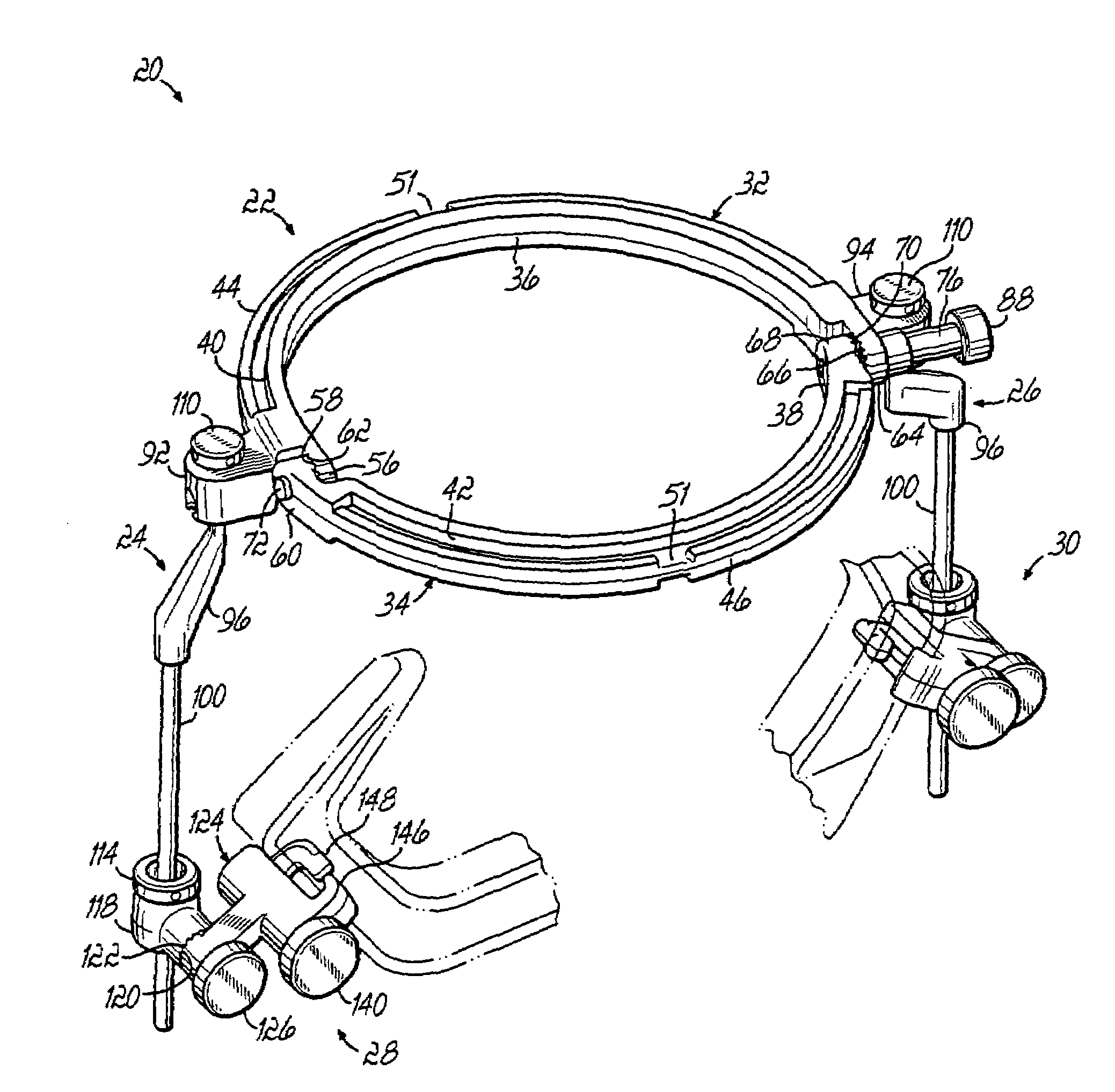
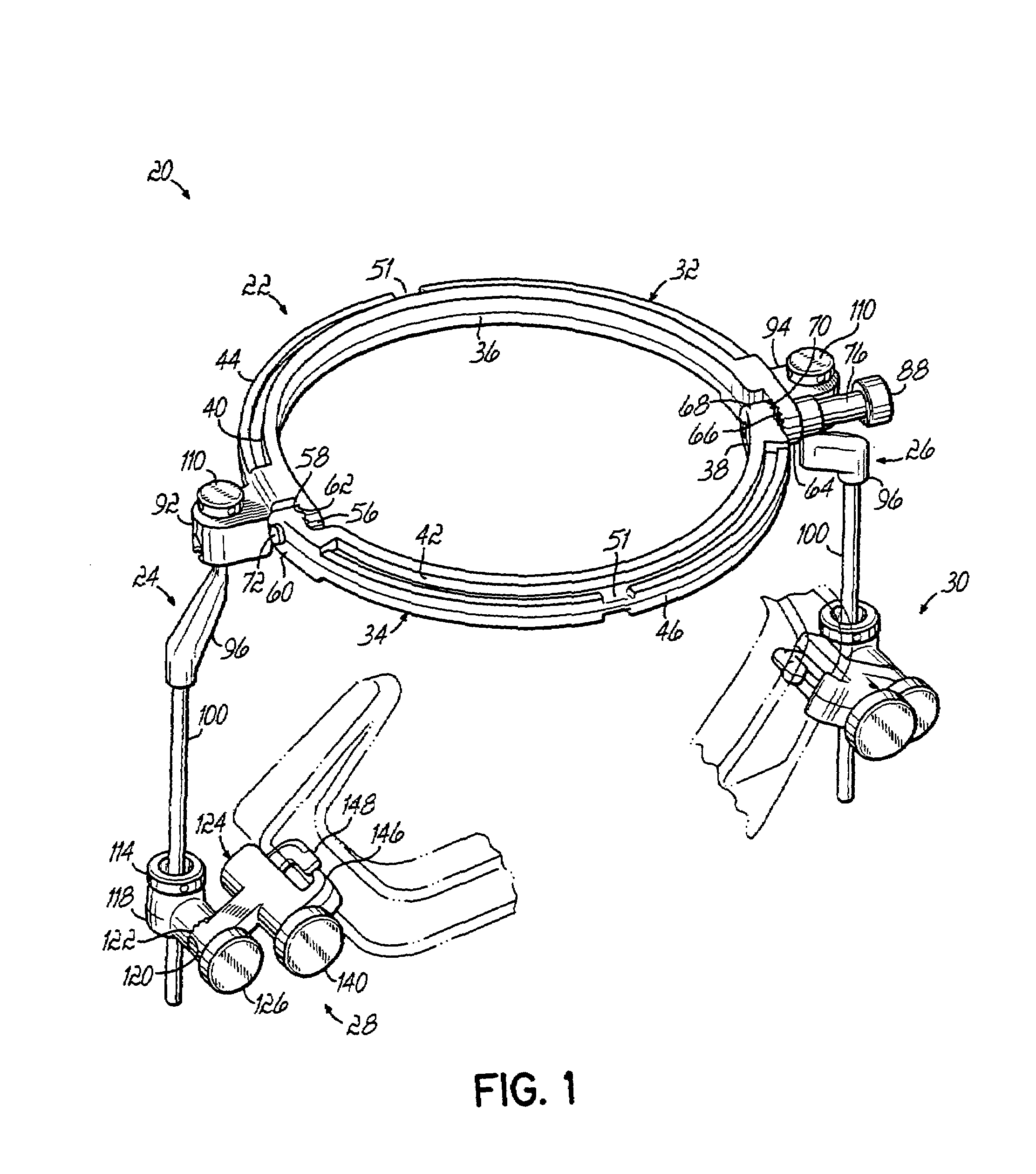
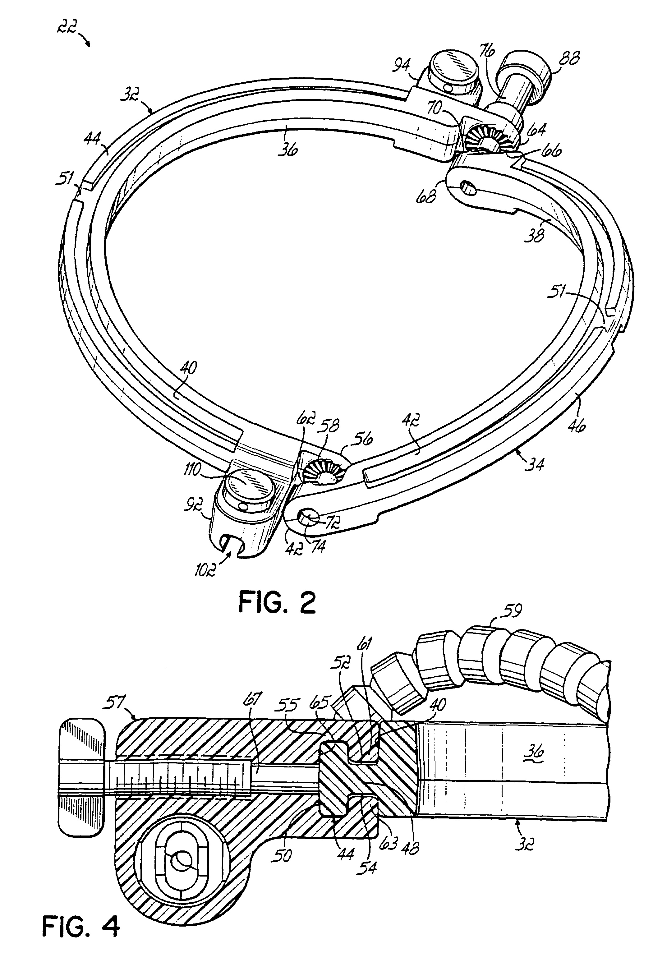
[0020]Referring to FIG. 1, a radiolucent, halo-style surgical retractor 20 is comprised of a radiolucent retractor ring 22 that is mounted on upper ends of radiolucent support brackets 24, 26. The support brackets are, in turn, mounted at their lower ends to radiolucent mounting clamps 28, 30. The retractor ring 22 is comprised of a radiolucent, curvilinear fixed member or half-ring 32 and a radiolucent, curvilinear movable member or half-ring 34. As shown in FIG. 2, the fixed and movable members 32, 34 have respective inner concave surfaces 36, 38 and respective outer convex surfaces 40, 42. Further, the fixed and movable members 32, 34 have respective radiolucent male couplings 44, 46 projecting radially outward from the respective convex surfaces 40, 42. The male couplings 44, 46 are substantially identical in construction and cross-sectional profile.

[0021]Referring to FIG. 4, the male coupling 44 has a radiolucent, curvilinear leg 48 with an inner or proximal end connected to th...


PUM


Abstract

A radiolucent halo-type retractor (20) having a radiolucent curvilinear fixed member (32) connected to a radiolucent curvilinear movable member (34). Each of the fixed and movable members has a radiolucent male coupling (44, 46) projecting outward from a convex surface (40, 42) to receive a female coupling of a retractor arm. The ends (60, 68) of the movable member are separated by a distance less than a distance separating the ends (56, 64) of the fixed member. Radiolucent starburst connectors (58, 62) are disposed on first ends of the fixed and movable members to secure the fixed and movable members at a desired angular orientation. Radiolucent starburst connectors (66, 70) are also disposed on second ends of the fixed and movable members to secure the fixed and movable members at a desired angular orientation. A pin (72) rotatably connects the first ends. A locking shaft (76) rotatably connects the second ends and is operable to lock the fixed and movable members in a desired orientation.

Description

[0001]This application is a 371 of International Patent Application No. PCT / US02 / 12513, filed on Apr. 19, 2002, which claims priority to Provisional Application Ser. No. 60 / 285,257, filed on Apr. 20, 2001, both hereby expressly incorporated by reference herein.FIELD OF THE INVENTION [0002]This invention relates generally to the field of surgical instruments, and more particularly, to a halo-style surgical retractor to facilitate holding bodily tissues, membranes, and vessels, retracted during cranial surgery.BACKGROUND OF THE INVENTION [0003]There are many different known surgical retractor components, for example, halo-style retractors and supporting components as well as flexible retractor arms. Halo-style retractors are often made of two hinged, generally semicircular half-rings, a first of which is affixed to supporting structure. A second half-ring is pivotable and adjustable with respect to the first half-ring about a generally diametric axis of rotation. Retractor arms and ot...

Claims


Application Information

Patent Timeline
Patent Type & Authority Patents(United States)
IPC IPC(8): A61B17/02A61B1/32A61B17/28A61B19/00
CPCA61B17/02A61B17/0293A61B17/0206A61B19/203A61B2017/00902A61B2017/00915A61B2017/2905A61B90/14
Inventor DINKLER, II, CHARLES E.EASTON, KEVIN R.MOWLAI-ASHTIANI, ALI
Owner INTEGRA LIFESCI
Why Eureka
Try Eureka