
Method for temporally editing videos

a temporally edited and video technology, applied in the field of image processing, can solve the problems of insufficient image scaling, limited cropping, and insufficient scaling, and achieve the effect of reducing artifacts and distortions of conten

Active Publication Date: 2012-10-16
MITSUBISHI ELECTRIC RES LAB INC
View PDF11 Cites 0 Cited by
  • Summary
  • Abstract
  • Description
  • Claims
  • Application Information

AI Technical Summary

Benefits of technology

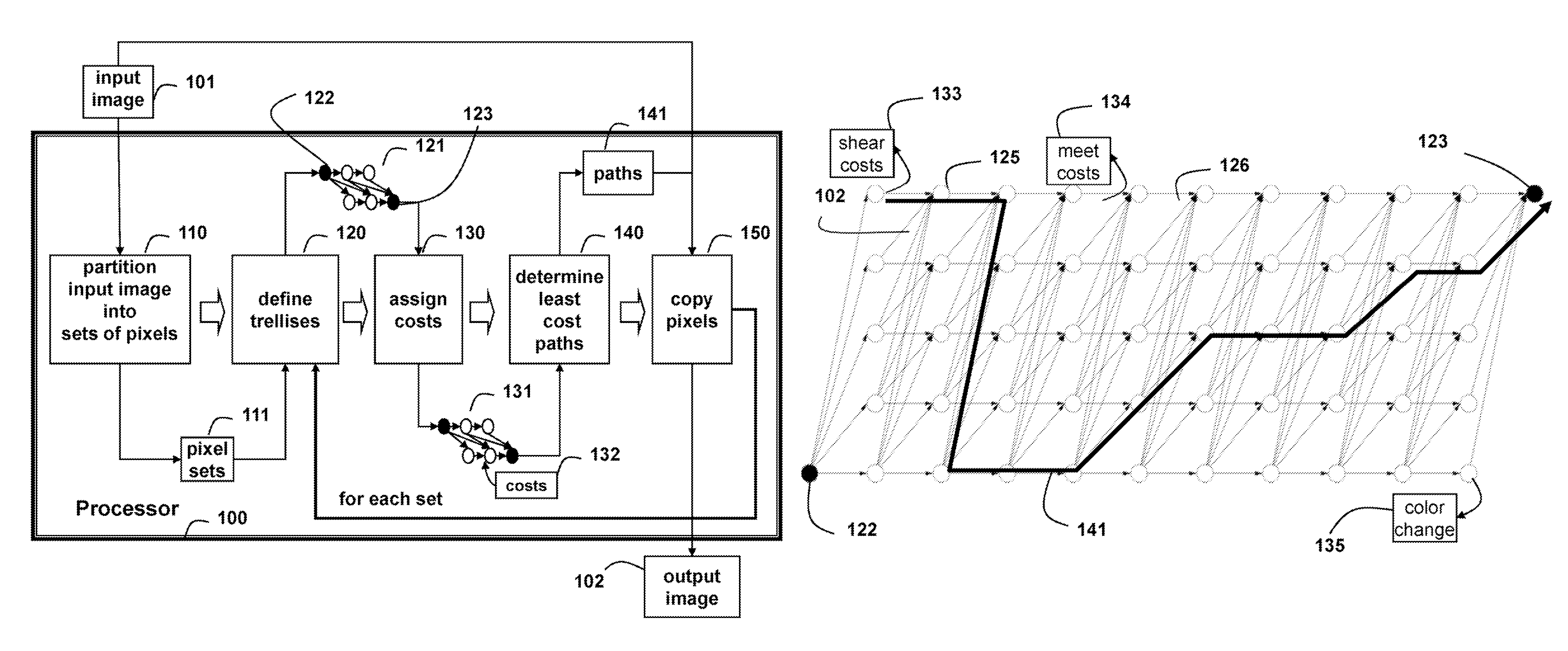
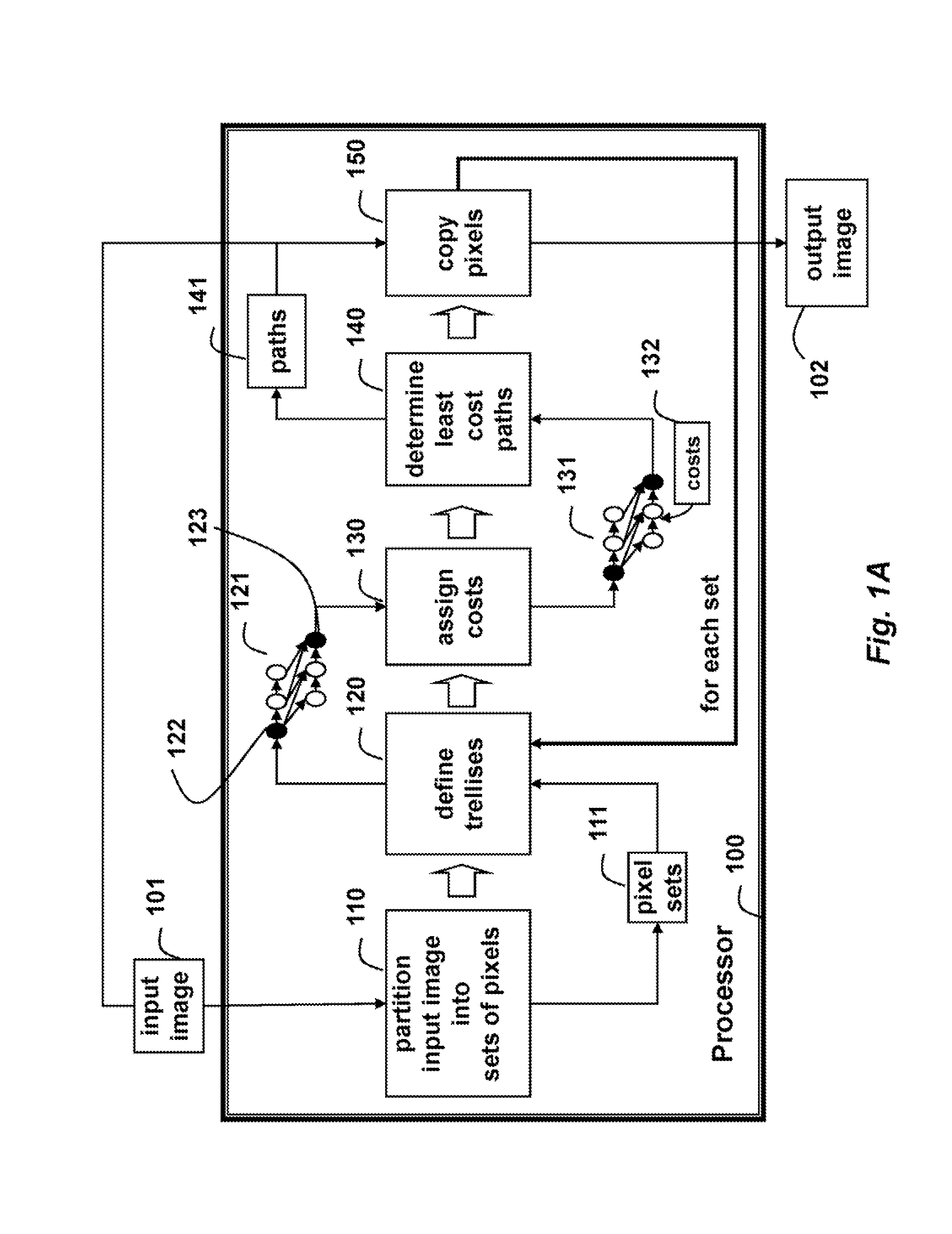
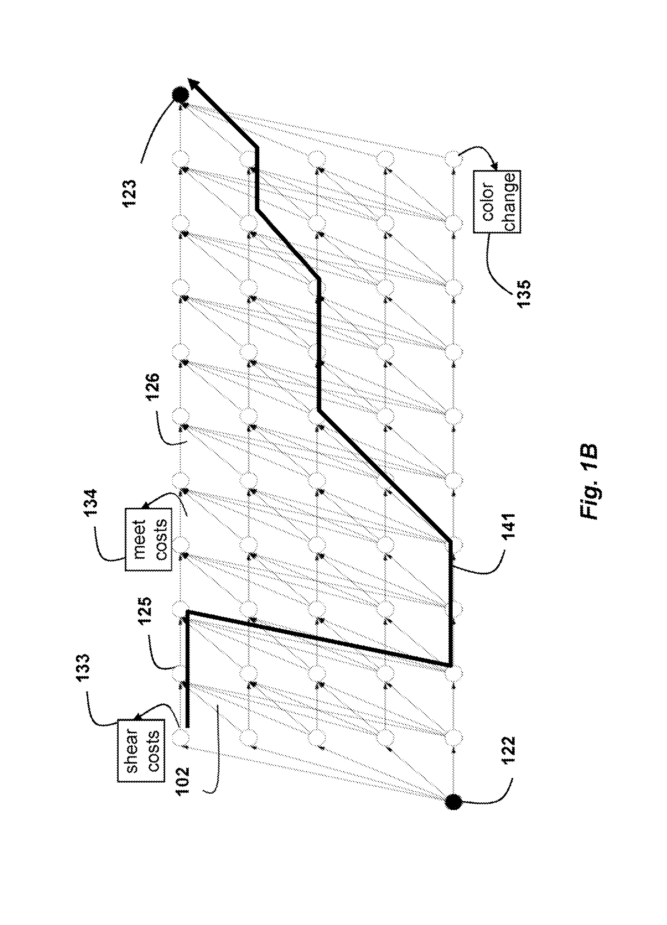
This patent describes a way to edit images and videos by moving, deleting, inserting, and modifying pixels. The method aims to create an output with minimal distortions and artifacts. For example, if a user specifies a new temporal length for a video, the method will rearranging pixels to achieve the desired length. Additionally, if a user specifies that a set of pixels should be shifted to a new time, the method will delete and fill in pixels around the moved pixels to make the change look natural. The method uses a graph to find the least noticeable sequence of edits and applies those edits to generate the output. Overall, this patent provides a technical solution for editing images and videos with precise and minimal changes.

Problems solved by technology

Image scaling is insufficient because it ignores the image content and typically can only be applied uniformly.
Scaling also does not work well when the aspect ratio of the image needs to change, because it introduces visual distortions.
Cropping is limited because it can only remove pixels from the image periphery.
However, seam carving often distorts and damages image contours.
The seams are not optimal for the target image dimensions, and a greedy sequential strategy precludes the use for videos.
Rubenstein et al., use a graph-cut reformulation that handles video, but the optimizer is impractically slow and still limited to greedy seam removal.
However, that method is vulnerable to unwanted embedding “catastrophes” where regions of the image invert and overlap over other regions, i.e., the pixel order is not necessarily preserved.

Method used


Image

  • Method for temporally editing videos
  • Method for temporally editing videos
  • Method for temporally editing videos

Examples


examples

[0101]FIG. 8 shows the darting pattern for removing 112 of 512 columns of pixels with a trellis of bandwidth of 12 and a girth 90 from an image 800, as determined by the method of this invention. In this example, darts were propagated from the center scanline using information back-propagated from the top and bottom scanlines.

[0102]FIG. 9 shows and example of removing darts as shown in image 800 from an input image 900 to obtain an output image 1000.

[0103]FIG. 10 shows the result after removal of the darts. Even though many disconnected groups of pixels are removed, contours are well preserved, even the pixel-wide tether lines 801 shown in FIG. 8. The prior art processing is shown in image 1001.

[0104]FIG. 10 shows the result of removing 112 columns then removing 40 rows in image 1000.

[0105]FIG. 11 shows a similar result obtained using convention seam carving in image 1001. Seam carving breaks coastline above the left astronaut and the tether line at bottom, clips the antenna at top,...


PUM


Abstract

A method edits an input video to produce an output video. Pixels of the input video are partitioned into sets of pixels, wherein the pixels in the sets are adjacent, and for each set of pixels performing the following steps. A trellis having nodes connected by directed links is constructed. Each node corresponds to one of the pixels in the set of pixels, and each node is associated with an action and location of the pixel in the output image. Costs are assigned to the nodes and the links, wherein the costs are on apparent motion in the input video. A least cost path is determined through the trellis. Then, for each node on the path, apply the action associated the node to the corresponding pixel in the input video to edit the corresponding pixel at the location in the output video associated with the node.

Description

RELATED APPLICATION[0001]This Continuation-in-Part application is related to Non-Provisional Application 12 / 356,398 “Method for Editing Images and Videos” by Matthew Brand filed Jan. 20, 2009, incorporated herein by reference.FIELD OF THE INVENTION[0002]This invention relates generally to image processing, and more particularly to editing video to different temporal lengths.BACKGROUND OF THE INVENTION[0003]The diversity and versatility of print and display devices imposes demands on designers of multimedia content for rendering and viewing. For instance, designers must provide different alternatives for web-content, and design different layouts for different rendering applications and devices, ranging from tiny “thumbprints” of images often seen in selections menus, small, low resolution mobile telephone screens, slightly larger PDA screens, to large, high resolution elongated flat panel displays, and projector screens. Adapting images to different rendering applications and devices...

Claims


Application Information

Patent Timeline
Patent Type & Authority Patents(United States)
IPC IPC(8): G06K9/36G06K9/03
CPCG06T3/0093G11B27/034G11B27/036G06T3/18
Inventor BRAND, MATTHEW E.
Owner MITSUBISHI ELECTRIC RES LAB INC
Learn More