Lens with embedded multilayer optical film for near-eye display systems

a multi-layer optical film and display system technology, applied in the field of lenses, can solve the problems of significantly reducing the optical performance of the lens, birefringent polymer layers tend to be more brittle, etc., and achieve the effect of high quality optical performance, minimal artifacts, and robustness

Active Publication Date: 2017-12-12
3M INNOVATIVE PROPERTIES CO
View PDF50 Cites 5 Cited by
  • Summary
  • Abstract
  • Description
  • Claims
  • Application Information

AI Technical Summary

Benefits of technology

[0005]In Near Eye Displays and similar systems, the lens portion of the glasses desirably combines world and augmented (projected) views, provides high quality optical performance with a minimum of artifacts, and is also robust enough to withstand normal handling and usage typical for eyeglasses.
[0006]Multilayer optical films that include a stack of polymer layers configured to selectively reflect light by constructive or destructive interference have been used now for many years in a variety of applications in which high quality optical performance, with minimal artifacts, is required, such as in backlit display applications for laptop computers. However, embedding such films into a lens to function as a beamsplitter, particularly where the beamsplitter is designed to be off-axis relative to the optical axis of the lens, and also where at least some of the polymer layers in the stack are birefringent, poses certain design challenges and is by no means a trivial undertaking. If the degree of misalignment between the optical axis of the lens and the orientation of the optical film is large enough, the optical film may meet or intersect an optical surface of the lens. Such an intersection results in a bifurcation of the optical surface, with an edge of the multilayer optical film forming a line of separation between the two portions of the bifurcated optical surface. Polymer layers that are birefringent tend to be more brittle than those that are isotropic, and the edge of a multilayer optical film that contains birefringent polymer layers can therefore tend to have more breaks, cracks, and / or delaminations at such edge than an alternative film that contains no birefringent layers. If present at the edge of the film, such breaks, cracks, and other edge defects have the potential to significantly diminish the optical performance of the lens, particularly since they are located at or near the optical surface of the lens, directly in the path of incident light rays and within the clear aperture of the optical system.
[0007]We have found that multilayer optical films containing birefringent polymer layers can be successfully embedded into lenses to provide a beamsplitting function that may be suitable for Near-Eye Displays and similar applications. If the degree of misalignment between the optical axis of the lens and the orientation of the multilayer optical film is such that an optical surface of the lens is bifurcated by the film, care can be taken to ensure that the edge of the multilayer optical film that forms a line of separation between the portions of the bifurcated optical surface does not have excessive defects such as breaks, cracks, or delaminations, thus allowing for high quality optical performance of the lens. Ensuring that the film edge has minimal edge defects can also or alternatively enhance product robustness by reducing the chance of fracturing of the lens at the film edge (e.g. due to an edge delamination that spreads throughout the film) in the presence of stresses that may occur in the lens during product fabrication, installation, or use.

Problems solved by technology

However, embedding such films into a lens to function as a beamsplitter, particularly where the beamsplitter is designed to be off-axis relative to the optical axis of the lens, and also where at least some of the polymer layers in the stack are birefringent, poses certain design challenges and is by no means a trivial undertaking.
Polymer layers that are birefringent tend to be more brittle than those that are isotropic, and the edge of a multilayer optical film that contains birefringent polymer layers can therefore tend to have more breaks, cracks, and / or delaminations at such edge than an alternative film that contains no birefringent layers.
If present at the edge of the film, such breaks, cracks, and other edge defects have the potential to significantly diminish the optical performance of the lens, particularly since they are located at or near the optical surface of the lens, directly in the path of incident light rays and within the clear aperture of the optical system.

Method used


Image

  • Lens with embedded multilayer optical film for near-eye display systems
  • Lens with embedded multilayer optical film for near-eye display systems
  • Lens with embedded multilayer optical film for near-eye display systems

Examples


Embodiment Construction

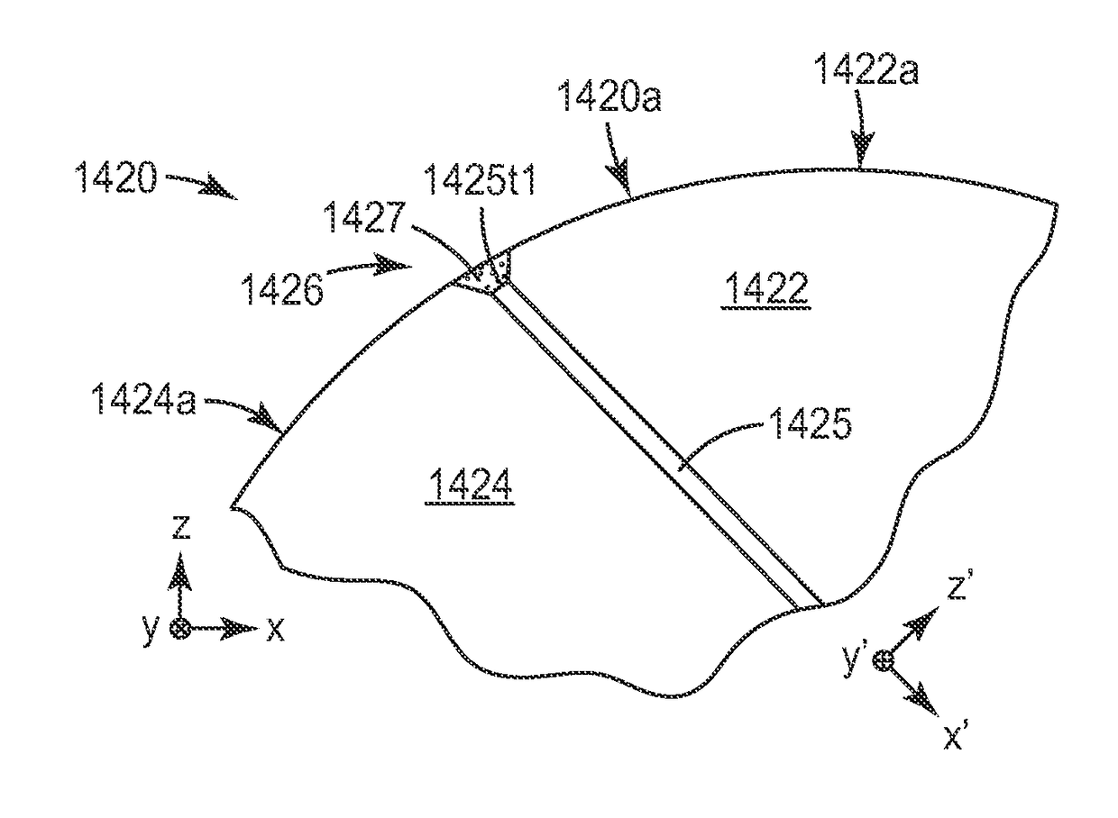
[0035]As mentioned above, we have developed lenses in which the lens is formed from at least two sections or bodies that are shaped to mate with each other, and a multilayer optical film is sandwiched between these two sections. The multilayer optical film is partially transmissive and partially reflective in order to give the lens a beamsplitting capability. The partial transmission and reflection may be primarily a function of polarization state of normally incident light (as with a broadband reflective polarizer), or may be primarily a function of optical wavelength (as with a notched filter), or may be a combination of these, and / or in combination with other characteristics. The multilayer optical film is oriented within the lens such that an edge or terminus of the film intersects an optical surface of the lens. The terminus separates smooth surfaces of each of the two lens sections, such smooth surfaces in combination providing an optical surface of the lens. Any edge defects ...


PUM

PropertyMeasurementUnit
average defect distanceaaaaaaaaaa
defect distanceaaaaaaaaaa

Abstract

A lens is formed from at least two sections or bodies that are shaped to mate with each other, and a multilayer optical film is sandwiched between these two sections. Smooth surfaces of each section combine to provide a first optical surface of the lens, e.g., a concave, convex, or flat optical surface. The multilayer optical film includes a stack of polymer layers configured to selectively reflect light by constructive or destructive interference, at least some of the polymer layers being birefringent. The multilayer optical film may thus be or comprise e.g. a reflective polarizer and / or a narrow band or otherwise notched reflector. The multilayer optical film has an extended terminus that separates the smooth surfaces of the two sections. Any edge defects such as cracks or delaminations that may exist along the extended terminus are characterized by an average defect distance of no more than 100 or 50 microns.

Description

FIELD OF THE INVENTION[0001]This invention relates generally to lenses and related optical components, with particular application to lenses that include a partially reflective element for purposes of beamsplitting. The invention also relates to associated articles, systems, and methods.BACKGROUND[0002]Optical beamsplitters are known. Some beamsplitters are made by cementing two prisms together with a reflective film in between. The reflective film typically extends between opposite edges of the beamsplitter. See e.g. U.S. Pat. No. 7,329,006 (Aastuen et al.)[0003]Lenses, including compound lenses in which two or more simple lenses are cemented together, are also known. U.S. Pat. No. 5,654,827 (Reichert) discusses lenses in which the lens is divided into two parts by a beamsplitter.[0004]Head-Up Displays or Head-Mounted Displays (collectively referred to herein as HUDs) can project an image that fills all or part of a user's field of view. Some HUDs use a combiner optic that integrat...

Claims


Application Information

Patent Timeline
Patent Type & Authority Patents(United States)
IPC IPC(8): G02B5/30G02B27/14G02B27/28G02B27/01G02B1/04G02B5/28
CPCG02B27/0172G02B5/28G02B27/142G02B27/283G02B2027/0178G02B1/041G02B5/287G02B5/305
Inventor OUDERKIRK, ANDREW J.BINDER, ERIN A.
Owner 3M INNOVATIVE PROPERTIES CO
Why Eureka
Try Eureka