Fiber-aligning optical switch

a fiber-aligning, optical switch technology, applied in the field of optical switches, can solve the problems of low efficiency, low reliability, high cost, etc., and achieve the effect of sufficient robustness

Inactive Publication Date: 2005-05-24
INTEL CORP
View PDF34 Cites 13 Cited by
  • Summary
  • Abstract
  • Description
  • Claims
  • Application Information

AI Technical Summary

Benefits of technology

[0012]In view of the above, it is an object of the invention to provide an optical switch for aligning one or more input fibers with one or more output fibers rapidly and reliably. In particular, the optical switch is to be sufficiently robust and low-cost for deployment in optical networks and other optical switching systems.
[0013]It is also an object of the invention to provide an optical switch whose frame and architecture enable configuration as a 1×2, 2×2 and N×M switch for single or gang operation.
[0014]These and other objects and advantages will become apparent upon reading the following description.
[0015]The objects and advantages of the invention are achieved by an optical switch that aligns a first fiber set with a second fiber set, where the first and second fiber sets can include as few as one fiber each. The switch has a primary frame for affixing the first fiber set and a switching frame for affixing the second fiber set opposite the first fiber set. The switching frame is flexibly attached to the primary frame. A first piezoelectric element is attached to the primary frame and to the switching frame such that it can displace the switching frame along a first linear direction relative to the primary frame. The optical switch also has a latching frame flexibly attached to the primary frame. The latching frame is provided for latching the switching frame in aligned positions between the first fiber set and second fiber set. In other words, the latching frame latches the switching frame when the fibers of the first and second fiber sets are in the desired switching positions.
[0016]In a preferred embodiment a second piezoelectric element is attached to the primary frame and the latching frame for engaging the latching frame with the switching frame in the aligned positions. In particular, the second piezoelectric element is configured to displace the latching frame between an engaged position in which the switching and latching frames are engaged and a disengaged position in which the switching and latching frames are disengaged. Most preferably, the second piezoelectric element moves the latching frame between the engaged and disengaged positions along a second linear direction, which is orthogonal to the first linear direction. The piezoelectric elements are controlled by a suitable control unit, e.g., a controlled voltage source.
[0017]In the same or in a different embodiment, the primary frame has a first V-groove set for affixing the fiber or fibers belonging to the first fiber set to the primary frame. Similarly, the switching frame has a second V-groove set for affixing the fiber or fibers belonging to the second fiber set to the switching frame.

Problems solved by technology

All-optical approaches promise extremely rapid switching speeds but have a number of significant drawbacks, including low efficiency, low reliability and high cost.
These limitations eliminate all-optical switches from applications in fiberoptic networks where high levels of reliability, longevity, switching precision and low cost are key.
The need to displace optical elements to achieve switching limits the speed and accuracy of these types of optical switches rendering them inadequate for fiber optic networks.
One drawback to mechanical switches, which bend fibers, is maintaining fiber planarity.
Specifically, the bending of a fiber is not a very controllable process and it is difficult to keep the fiber in one plane as it is being bent.
Therefore, switches relying on bending fibers suffer from alignment problems, thus rendering them inadequate for high speed and high accuracy optical networks.
Another drawback of prior art mechanical switches that utilize piezoelectric elements are difficulties in maintaining positioning accuracy and positioning repeatability.
Aging and varying operational conditions like voltage or temperature fluctuations limit positioning accuracy and repeatability during the devices lifetime.
The prior art latching interfaces are passive and introduce additional parts that are prone to wear.

Method used


Image

  • Fiber-aligning optical switch
  • Fiber-aligning optical switch
  • Fiber-aligning optical switch

Examples


Embodiment Construction

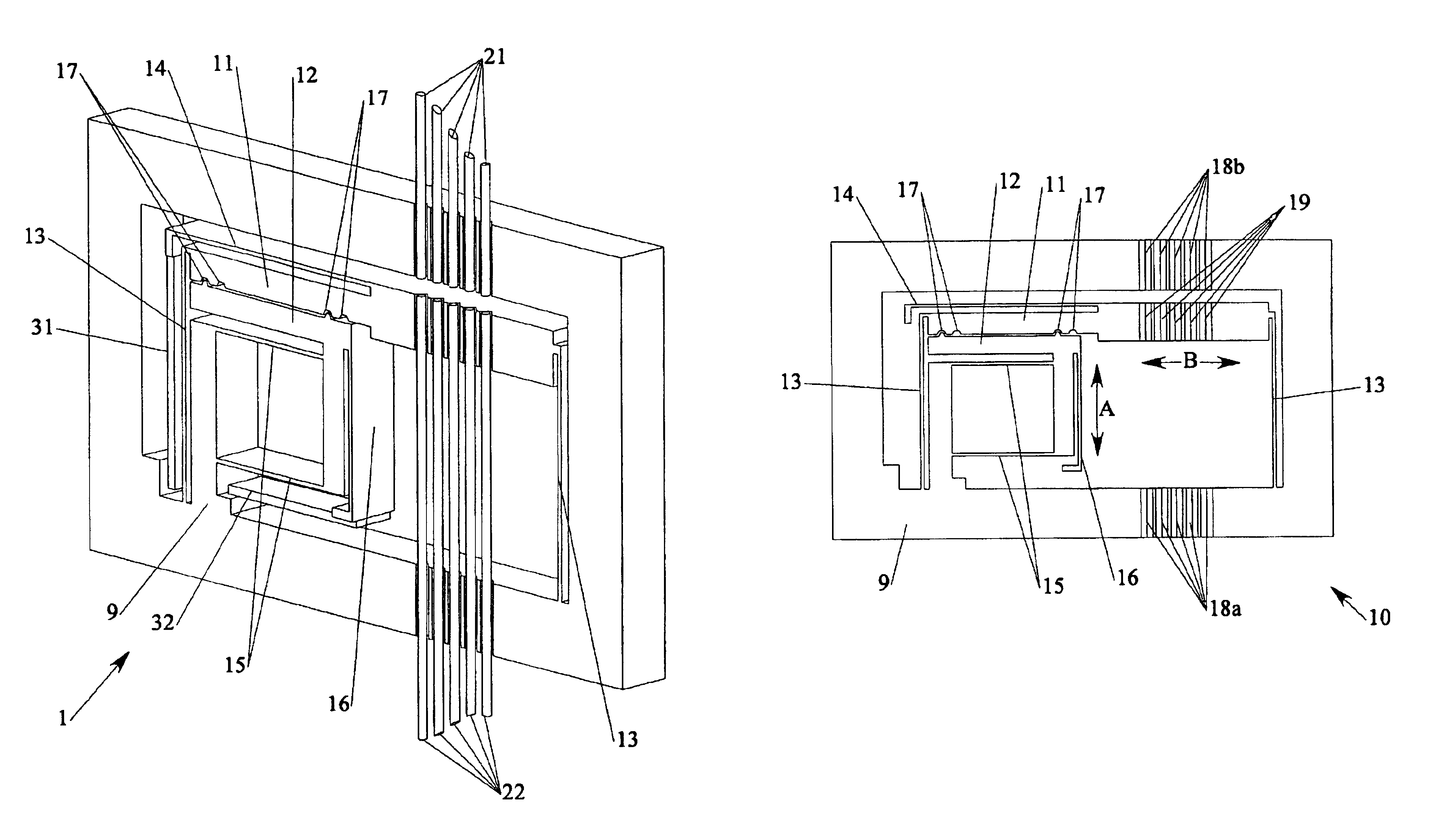
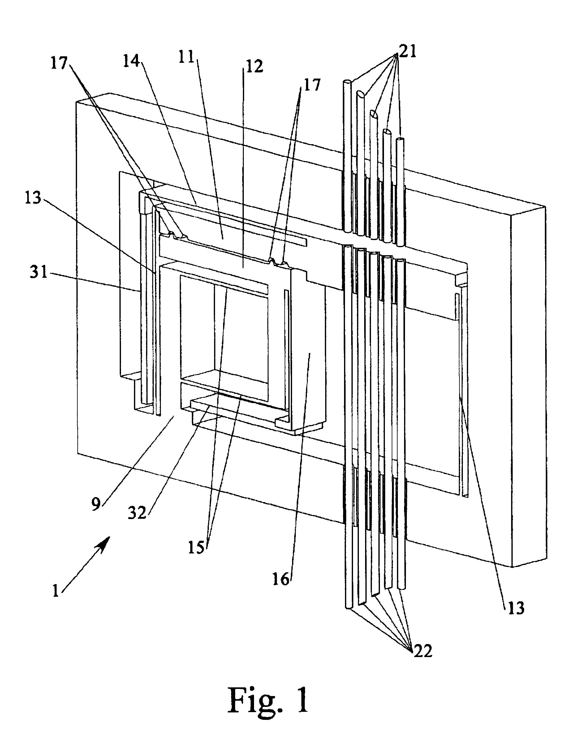
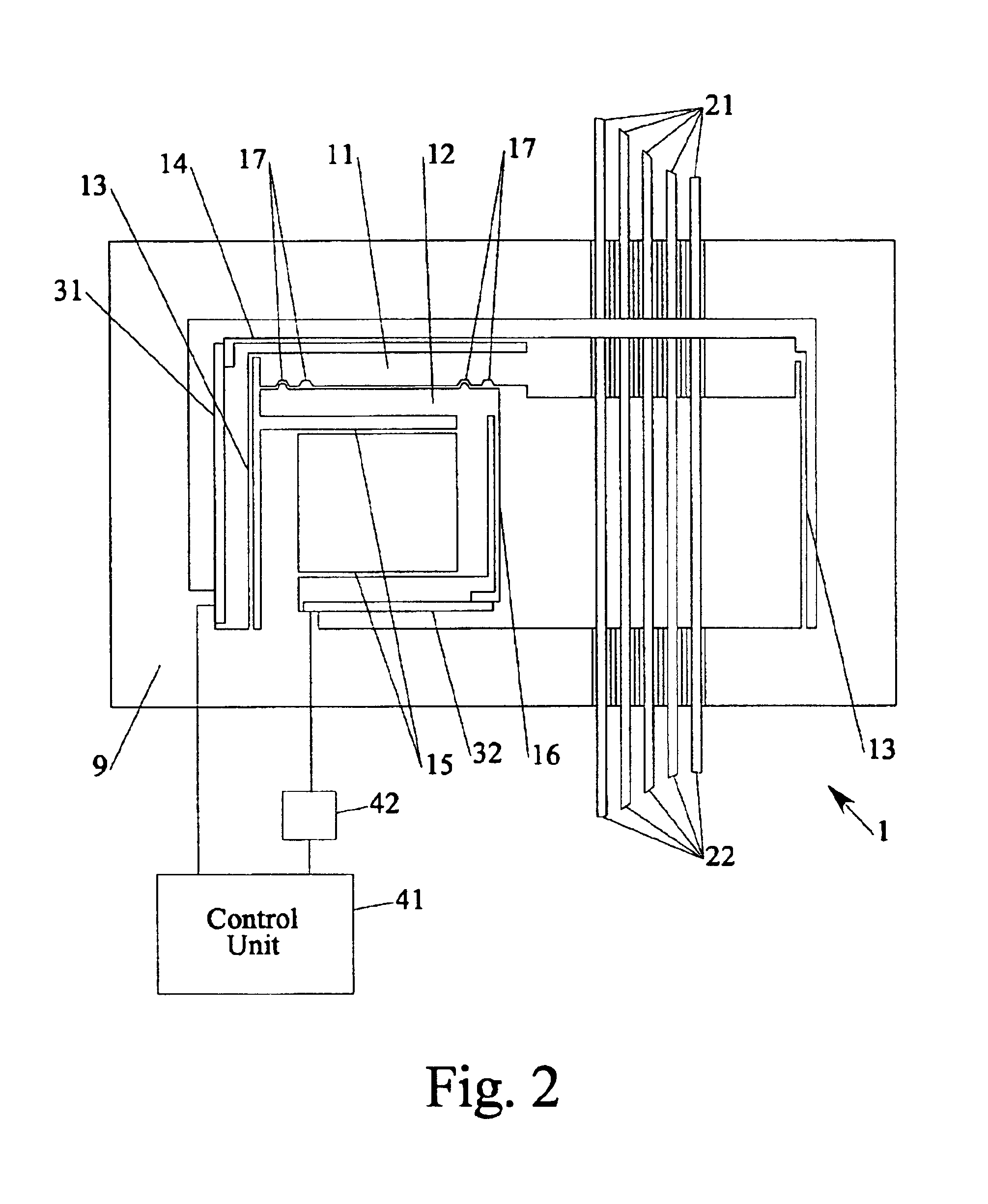
[0028]FIGS. 1 and 2 illustrate a preferred embodiment of an optical switch 1 in accordance with the invention. A primary frame 9 includes a switching frame 11 and a latching frame 12, which are flexibly connected to a body 10 via first and second legs 13, 15 (see also FIG. 3). The primary frame 9 surrounds the assembly and provides for stiffness and for attachment of a housing (not shown).

[0029]The optical switch 1 features two piezoelectric elements 31, 32. The first piezoelectric element 31 is part of a switching mechanism that performs the mechanical switching. The switching frame 11 is also part of the switching mechanism. A latching mechanism includes a second piezoelectric element 32 and the latching frame 12, which is actuated by the second piezoelectric element 32. Both piezoelectric elements 31, 32 are well-known bending elements that bend in response to a voltage applied by a control unit 41.

[0030]The piezoelectric elements 31, 32 are bonded with one end on the primary fra...


PUM


Abstract

A mechanical optical switch provides an active switching mechanism and an active latching mechanism that are both actuated by piezoelectric elements. The switching mechanism includes a switching frame at which fiber ends are attached to be switched along an opposing array of fixed fiber ends. The active latching mechanism provides for a fast switching of the switching mechanism and a reliable holding of the switching positions. The elements of the switching mechanism and the latching mechanism are monolithically fabricated from a wafer. The piezoelectric elements are integrated by bonding. The switch is substantially free of gliding friction, which reduces switching forces and makes the switch highly reliable over an extended lifetime.

Description

FIELD OF THE INVENTION[0001]The present invention relates generally to optical switches and in particular to mechanically actuated optical switches, which achieve switching by aligning fibers.BACKGROUND OF THE INVENTION[0002]The ability to switch optical signals is fundamental to further advances in many fields of optics. For example, in optical communications networks it is necessary to efficiently and rapidly switch signals propagating via waveguides, such as optical fibers. Specifically, what is required are optical 1×2 and 2×2 switches as well as more general N×M switches capable of single or gang operation.[0003]The optical switching techniques taught by the prior art can generally be grouped into all-optical and mechanical approaches. All-optical approaches promise extremely rapid switching speeds but have a number of significant drawbacks, including low efficiency, low reliability and high cost. These limitations eliminate all-optical switches from applications in fiberoptic ...

Claims


Application Information

Patent Timeline
Patent Type & Authority Patents(United States)
IPC IPC(8): G02B6/35
CPCG02B6/3508G02B6/3586G02B6/3546G02B6/3578G02B6/358G02B6/355
Inventor SPRAGUE, RANDALL B.NOVACK, MITCH
Owner INTEL CORP
Why Eureka
Try Eureka