Feedback compensation method and circuit for an acoustic amplification system, and hearing aid device employing same

a technology of acoustic amplification and compensation method, which is applied in the direction of deaf-aid sets, transducers acoustic reaction prevention, electrical apparatus, etc., can solve the problems of reducing the usefulness of hearing aid devices for wearers, unwanted acoustic feedback between auditory transducers and microphones, and beyond the stability limit of amplifiers, so as to achieve effective and rapid feedback compensation and high sound quality

Inactive Publication Date: 2008-05-29
WEIDNER TOM
View PDF9 Cites 7 Cited by
  • Summary
  • Abstract
  • Description
  • Claims
  • Application Information

AI Technical Summary

Benefits of technology

[0010]An object of the present invention is to provide a feedback compensator, a hearing aid device with a feedback compensator, a method to compensate a feedback signal in an acoustic amplification system that enable an effective and rapid feedback compensation with high sound quality.

Problems solved by technology

In hearing aid devices, a problem commonly exists of unwanted acoustic feedback between an auditory transducer and a microphone.
The cause of feedback is the existence of a path between the amplified output and input that allows a component of the amplified input signal at a particular frequency to proceed back to the input, which is beyond the stability limit of the amplifier.
In the context of hearing aid amplification, a feedback can cause whistling noises or other interferences and thereby significantly reduce the usefulness of the hearing aid device for the wearer, or even reduce it to zero.
Given use of feedback compensation filters, artifacts and / or unintentional distortion of the input signal can occur.
The limitation of the frequency range has the disadvantage that it is implemented with a filter that sets the unstable frequency range according to the set or fixed characteristics of the filter.
This quickly leads to a limitation of the frequency range that is too wide, too narrow, or completely false, with a correspondingly deficient function of the feedback compensator, and the hearing aid device.

Method used


Image

  • Feedback compensation method and circuit for an acoustic amplification system, and hearing aid device employing same
  • Feedback compensation method and circuit for an acoustic amplification system, and hearing aid device employing same
  • Feedback compensation method and circuit for an acoustic amplification system, and hearing aid device employing same

Examples


Embodiment Construction

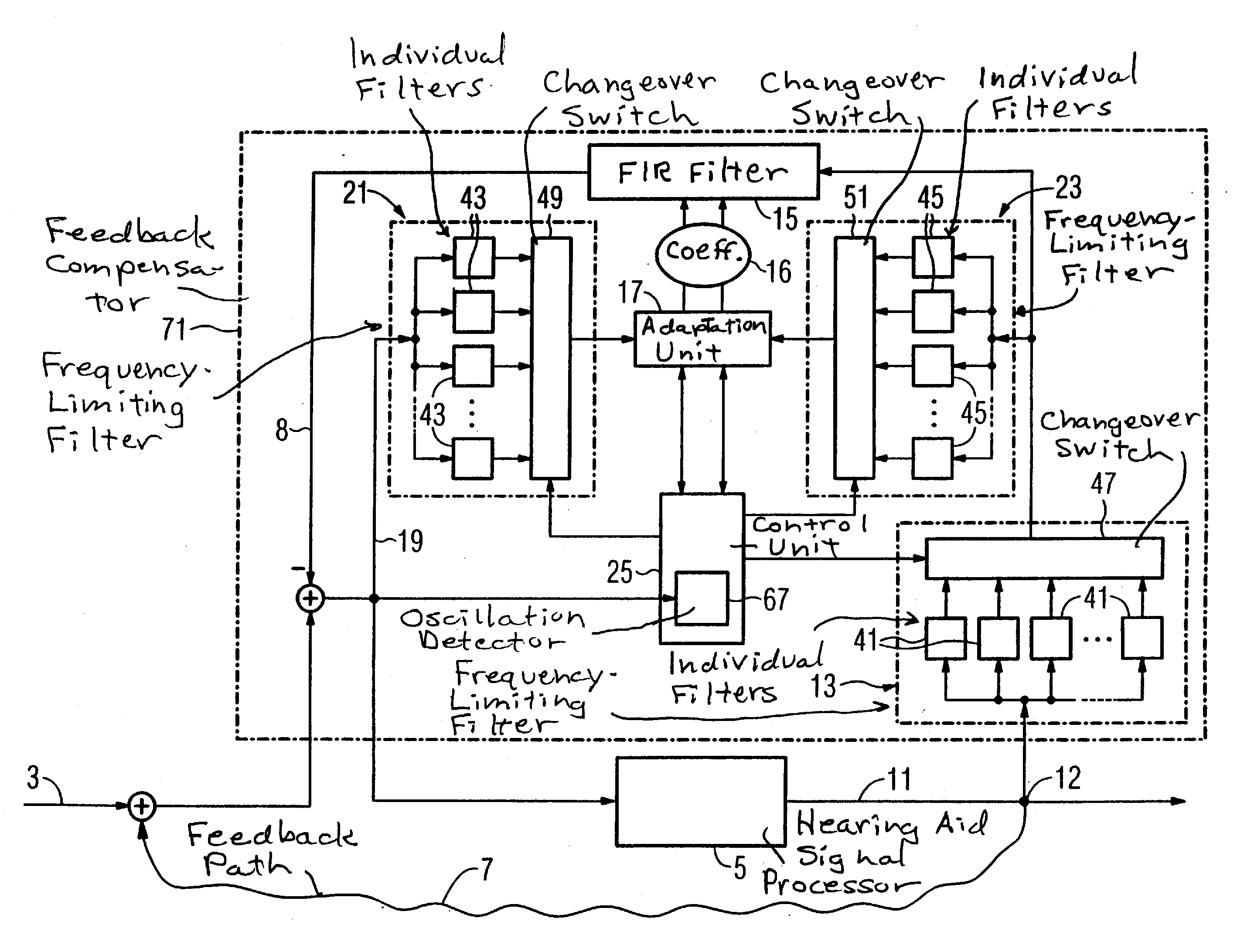
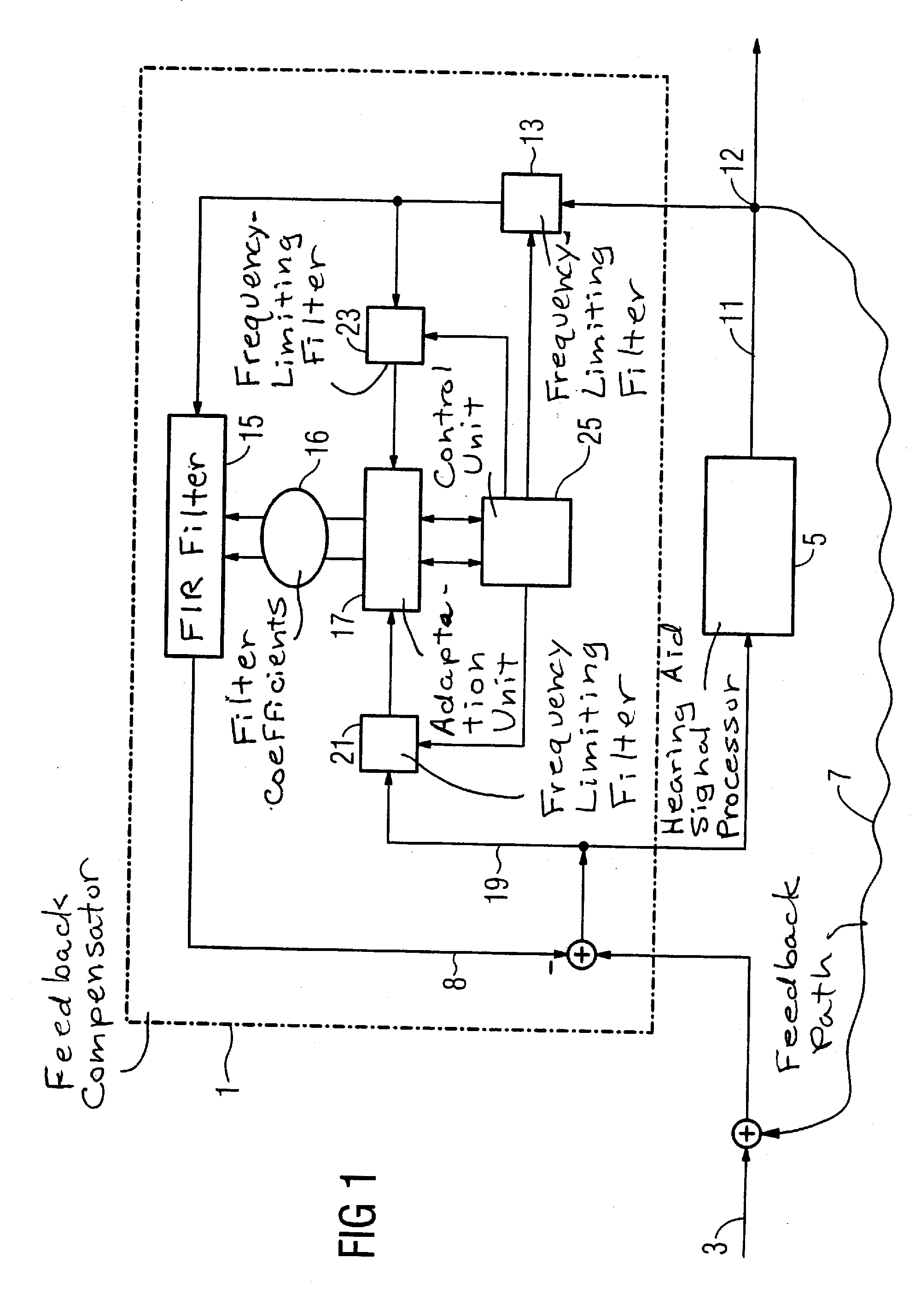
[0045]FIG. 1 is a schematic overview of a feedback compensator 1 that also enables a qualitatively good amplification of an acoustic input signal 3 with a hearing aid device signal processor 5, in the event that a feedback path is present, the frequency range of which can change due to varying external conditions. The feedback path 7 is, for example, determined by the diameter and by the position of the ventilation aeration holes of an in-the-ear hearing aid device as well as by an imperfect termination of the in-the-ear hearing aid device with the ear. Changes of the feedback path 7 also ensue when the acoustic surroundings change, for example when a helmet is put on or taken off.

[0046]The feedback compensator 1 is able to adapt the frequency range of the compensation signal 8 to the changing frequency range of the feedback path 7. For this, the feedback compensator 1 generates the compensation signal 8 in the following way. A small part of the output signal 11 of the hearing aid d...


PUM


Abstract

In a feedback compensation method and a feedback compensator in an acoustic amplification system such as a hearing aid, an adaptive feedback compensation filter generates a compensation signal from the amplified output signal, and one or more filters restrict the frequency range in which the compensation signal is generated. These filters are adaptable with regard to their filter function during the operation of the feedback compensator. The adaptation ensues with an analysis and control unit that checks the frequency range affected by the feedback and adapts the filter functions of the filters to it. The checking ensues, for example, by a comparison of the filter function of the feedback compensation filter with the filter functions of the filters to restrict the frequency range, or with the use of an oscillation detector.

Description

RELATED APPLICATION[0001]The present application is a continuation of application Ser. No. 10 / 659,230, filed Sep. 10, 2003 (now abandoned).BACKGROUND OF THE INVENTION[0002]1. Field of the Invention[0003]The present invention concerns a method and a feedback compensator in an acoustic amplification system to compensate a feedback signal that occurs in a feedback path upon amplification of an input signal, of the type having an adaptive feedback compensation filter that generates a compensation signal based on the amplified output signal. The invention also applies to a hearing aid device with such a feedback compensator, and operable according to the method.[0004]2. Description of the Prior Art[0005]In hearing aid devices, a problem commonly exists of unwanted acoustic feedback between an auditory transducer and a microphone. The cause of feedback is the existence of a path between the amplified output and input that allows a component of the amplified input signal at a particular fr...

Claims


Application Information

Patent Timeline
Patent Type & Authority Applications(United States)
IPC IPC(8): H04R25/00H04R3/02
CPCH04R25/453H04R3/02
Inventor WEIDNER, TOM
Owner WEIDNER TOM
Why Eureka
Try Eureka