Locking nail and targeting apparatus

Active Publication Date: 2007-06-19
STRYKER EURO OPERATIONS HLDG LLC
View PDF15 Cites 19 Cited by
  • Summary
  • Abstract
  • Description
  • Claims
  • Application Information

AI Technical Summary

Benefits of technology

[0005]It is the object of the invention to provide a locking nail and a targeting apparatus which, using a simple method to make it

Problems solved by technology

A problem in employing locking nails, when inserted, is how to identify the position of the cross-bores to drill a hole into the corticalis in the proper place from outside.
The disadvantage of using the targeting apparatus working with X-rays is that both the operator an

Method used


Image

  • Locking nail and targeting apparatus
  • Locking nail and targeting apparatus
  • Locking nail and targeting apparatus

Examples


Embodiment Construction

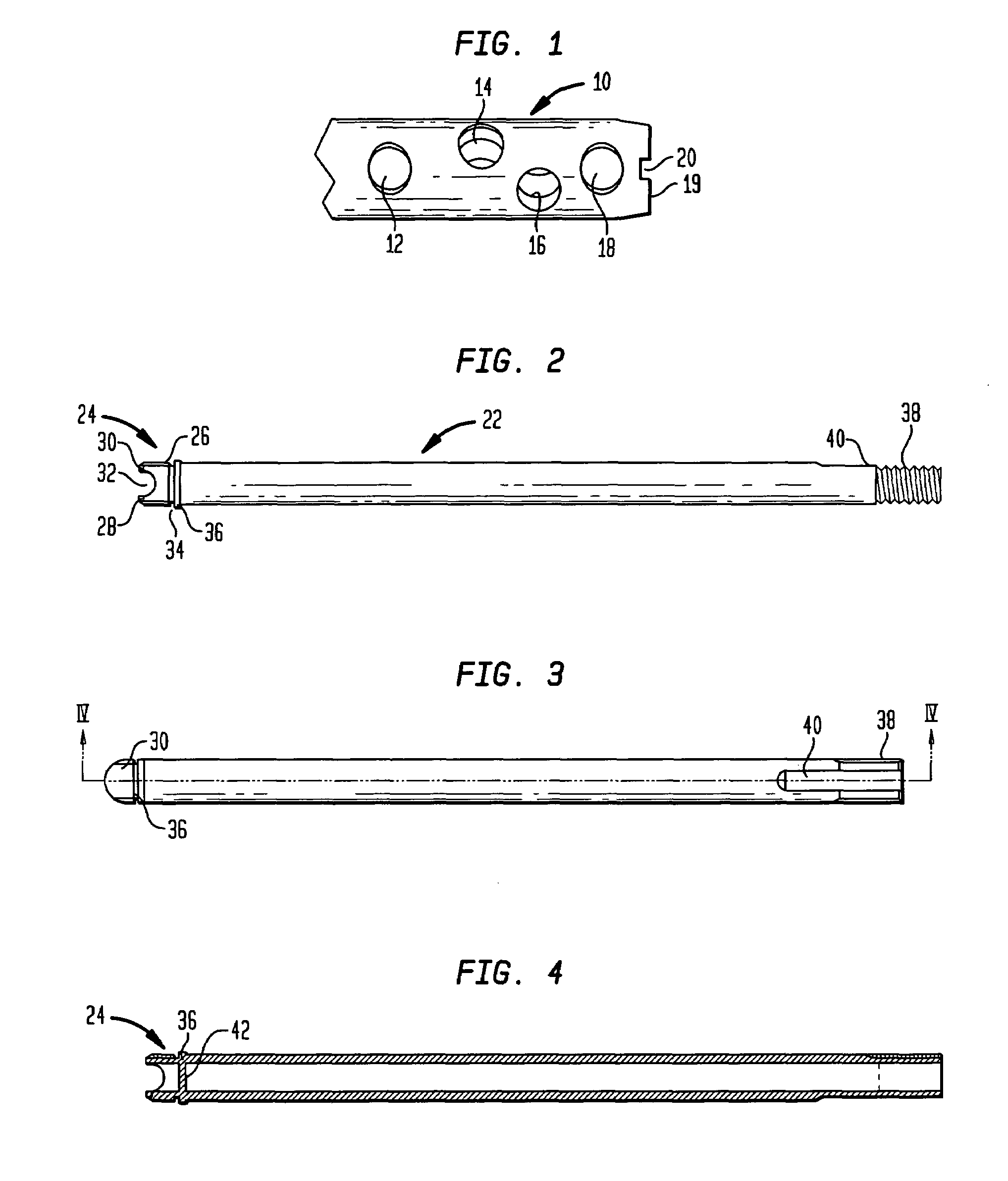
[0030]FIG. 1 shows the distal end of a locking or supracondylar nail 10. The locking nail is provided with four cross-bores 12, 14, 16 and 18 which serve for receiving bone screws and / or condylus screws to locate the locking nail both axially and radially in the bone. On the end face 19, locking nail 10 is provided with two recesses 20 the nearest one of which is shown and the second being spaced around the nail from the other at an angle of 180° in FIG. 1. In the preferred embodiment, recess 20 is of a rectangular shape. In the locking nail illustrated, the cross-bore 18 is at a distance of 6 mm from the free end of the nail. Not shown in FIG. 1 is a female thread which is provided inside the locking nail and which from the end 19 of the locking nail extends beyond the beginning of the cross-bore 18.

[0031]FIG. 2 shows a nail retention screw 22. The end 24 is provided for connection to locking nail 10. End 24 has a male thread 26 which corresponds to the abovementioned female thread...


PUM


Abstract

A locking nail for treating fractures of tubular bones has at least one cross-bore is provided at one end for the reception of a bone screw. The nail has a female thread at the end with the cross-bore for connection to a nail retention screw. The nail has an anti-rotation feature to anti-rotationally secure the rotational position of a joining sleeve which joins a targeting apparatus relative to the locking nail.

Description

BACKGROUND OF THE INVENTION[0001]The present invention relates to a locking nail to treat fractures of tubular bones. The invention also relates to an aiming or targeting apparatus for a locking nail.[0002]Locking nails for treating fractures of, for example, a femur, humerus and tibia, are known. It is common for locking nails to have cross-bores at the distal end and at least one cross-bore at the proximal end. Typically, bone screws are passed through the cross-bores which screws have been screwed into the corticalis at the opposite side of the bone. The bone screws secure the locking nail axially and rotationally. If supracondylar nails are used condylus screws may also be passed through the cross-bores.[0003]A problem in employing locking nails, when inserted, is how to identify the position of the cross-bores to drill a hole into the corticalis in the proper place from outside. A number of aiming or targeting apparatus have become known, which work with X-rays to identify the ...

Claims


Application Information

Patent Timeline
IPC IPC(8): A61B17/58A61B17/17A61B17/90
CPCA61B17/1725
Inventor ZANDER, NILSCREMER, AXEL
Owner STRYKER EURO OPERATIONS HLDG LLC
Why Eureka
Try Eureka