
Drag adjustment device for a dual-bearing reel

a dual-bearing, adjustment device technology, applied in the direction of reels, applications, fishing, etc., can solve the problems of lever operation and difficult operation of the drag adjustment lever, and achieve the effect of less prone to disturb the lever operation

Active Publication Date: 2007-06-26
SHIMANO INC
View PDF17 Cites 26 Cited by
  • Summary
  • Abstract
  • Description
  • Claims
  • Application Information

AI Technical Summary

Benefits of technology

[0012]An object of the present invention is to provide a drag adjustment device of a lever drag mechanism which is less prone to disturb lever operation in the operation for pressing a positioning block. Another object of the present invention is to provide a drag adjustment device that emits a sound without disturbing drag lever operation. Still yet another object of the present invention is to provide a clicking feeling without disturbing drag lever operation.
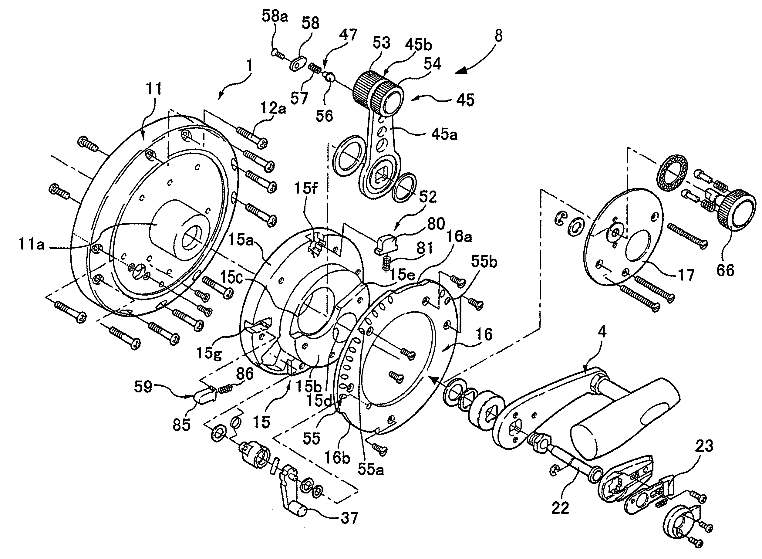
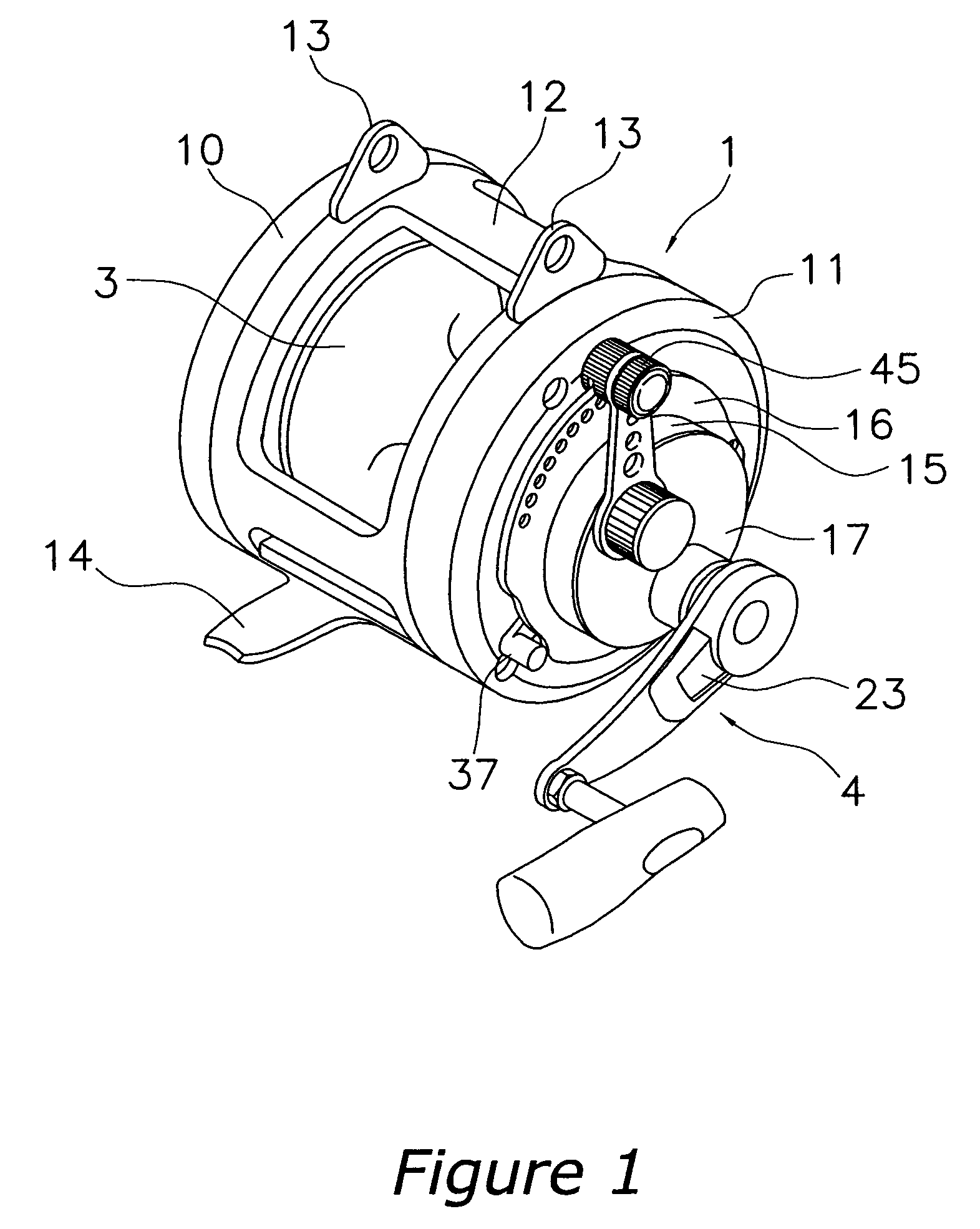
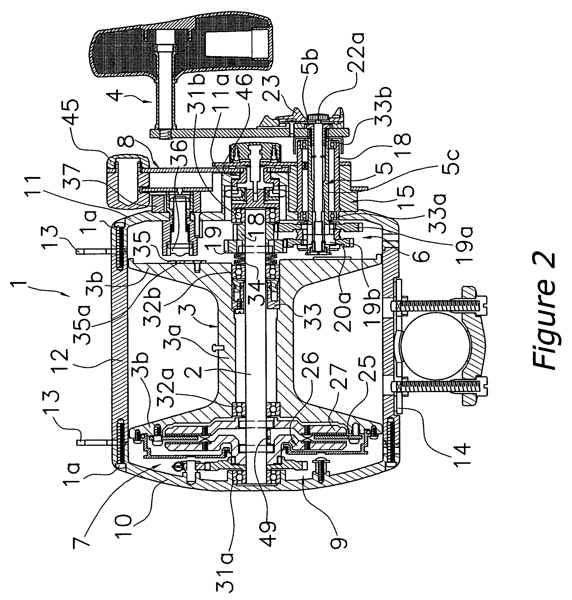
[0014]The drag adjustment lever is positioned in the intermediate position by the intermediate positioning mechanism. When the drag adjustment lever is operated from the intermediate position to the maximum position, the drag adjustment lever is released by the positioning block. In order to release the drag adjustment lever, the angler operates the drag adjustment lever toward the maximum position, while pressing the positioning block with the finger or thumb that operates the drag adjustment lever. During the pivoting operation, the sound-emitting pin repeatedly collides with the sound-emitting recessed portions to emit sound. The sound-emitting recessed portions are provided from the free position to the maximum position except in the region where the positioning block can retreat. Accordingly, the sound-emitting pin does not sound in the region where the sound-emitting recessed portions are not provided and the positioning block can retreat. In this construction, a sound is not emitted from the free position to the maximum position in the region where the positioning block is able to retreat, but is emitted in another region. Accordingly, resistance due to the collision of the sound-emitting pin with the sound-emitting recessed portions does not arise in the region where the positioning block can retreat. Therefore, even in the operation for pressing a positioning block, the force for operation corresponding to the resistance due to the sounding mechanism does not increase; thus, lever operation is less prone to be disturbed. In addition, a sound is emitted and a clicking feeling is provided except in the region where the positioning block is able to retreat.
[0017]Formation of the sound-emitting recessed portions is facilitated since through holes are provided in the lever guide nearest to the drag adjustment lever as the sound-emitting recessed portions. In addition, since the lever guide is a plate member that protrudes in an arc shape, it is possible to emit a crisp sound.
[0018]The drag adjustment device for a dual-bearing reel according to a fourth aspect of the present invention is the drag adjustment device according to any of the first through third aspects of the present invention, wherein the drag adjustment device further comprises a moving mechanism for moving the spool in the axial direction relative to a rotary shaft of the spool by the pivoting of the drag adjustment lever. In this construction, moving the rotary shaft of the spool can adjust the drag force.

Problems solved by technology

This disturbs lever operation and causes difficult operation of the drag adjustment lever toward the maximum position.

Method used


Image

  • Drag adjustment device for a dual-bearing reel
  • Drag adjustment device for a dual-bearing reel
  • Drag adjustment device for a dual-bearing reel

Examples


Embodiment Construction

[0033]Selected embodiments of the present invention will now be explained with reference to the drawings. It will be apparent to those skilled in the art from this disclosure that the following description of one embodiment of the present invention is provided for illustration only and not for the purpose of limiting the invention as defined by the appended claims and their equivalents.

[0034]As used herein to describe the present invention, the following directional terms “forward, rearward, left, right, upward, downward, vertical, horizontal, above, below and transverse” as well as any other similar directional terms refer to those directions of a fishing rod equipped with the dual bearing reel in accordance with the present invention. Accordingly, these terms, as utilized to describe the present invention should be interpreted relative to a fishing rod equipped with the present invention from a viewpoint behind the fishing rod and the dual bearing reel.

[0035]Referring initially to...


PUM


Abstract

A drag adjustment device for a dual-bearing reel that adjusts the drag force of a lever drag mechanism includes a drag adjustment lever, an intermediate positioning mechanism and a drag adjustment sounding mechanism. The drag adjustment lever is pivotably attached to the reel unit about a spool shaft between a free position corresponding to a drag free state and a maximum position corresponding to a maximum drag state of the lever drag mechanism. The intermediate positioning mechanism includes a positioning block that is attached to the reel unit at the intermediate position between the free position and the maximum position so as to be able to advance or retreat. The positioning block contacts the drag adjustment lever to position the drag adjustment lever at the intermediate position. The drag adjustment sounding mechanism sounds in response to the pivoting of the drag adjustment lever.

Description

CROSS-REFERENCE TO RELATED APPLICATIONS[0001]This application claims priority to Japanese Patent Application Nos. 2004-213155, 2004-243752 and 2004-359574. The entire disclosures of Japanese Patent Application Nos. 2004-213155, 2004-243752 and 2004-359574 are hereby incorporated herein by reference.BACKGROUND OF THE INVENTION[0002]1. Field of the Invention[0003]The present invention generally relates to an adjustment device. More specifically, the present invention relates to a drag adjustment device for a dual-bearing reel that adjusts the drag force of a lever drag mechanism to apply a braking force to a spool in the dual-bearing reel.[0004]2. Background Information[0005]Generally, a dual-bearing reel is furnished with a drag mechanism which brakes the rotation of a spool in the line releasing direction. Among drag mechanisms, a lever drag mechanism has excellent operability and drag adjusting accuracy in contrast with a star drag mechanism. Thus, the lever drag mechanism is commo...

Claims


Application Information

Patent Timeline
Patent Type & Authority Patents(United States)
IPC IPC(8): A01K89/033
CPCA01K89/006A01K89/015A01K89/033
Inventor HIRAYAMA, HIROKAZUIWABUCHI, MASAKAZU
Owner SHIMANO INC
Learn More