
Mounting structure of a circuit board connector

a technology of mounting structure and circuit board, which is applied in the direction of coupling device connection, coupling device details, printed circuits, etc., can solve problems such as contributing to the downsizing

Inactive Publication Date: 2007-06-26
YAZAKI CORP
View PDF16 Cites 2 Cited by
  • Summary
  • Abstract
  • Description
  • Claims
  • Application Information

AI Technical Summary

Benefits of technology

The present invention provides a mounting structure for a circuit board connector that can be secured to a circuit board without creating excessive stress on the circuit board. The mounting structure includes a connector housing and terminals that are conductively connected to the circuit board. The connector housing is located closer to the case than the circuit board and secured to screw retaining portions of the case. This prevents any unwanted stress produced during the coupling of the connector housing to the mating connector from affecting the second contactors of the terminal soldered to the circuit board. The mounting structure also allows for the connector housing to be prevented from turning when it is mounted to the case, which further reduces stress on the circuit board. Overall, this mounting structure provides a secure and reliable connection between the circuit board and the connector.

Problems solved by technology

Also, since the connector housing is located closer to the case between the circuit board and the case, the housing can hardly extend outwardly from the circuit board thus contributing to the downsizing.

Method used


Image

  • Mounting structure of a circuit board connector
  • Mounting structure of a circuit board connector
  • Mounting structure of a circuit board connector

Examples


Embodiment Construction

[0025]A mounting structure of a circuit board connector according to a preferred embodiment of the present invention will be described hereinafter.

[0026]A circuit board connector according to the embodiment is arranged to conductively connect with a circuit board installed in a case as being fixedly mounted to the case.

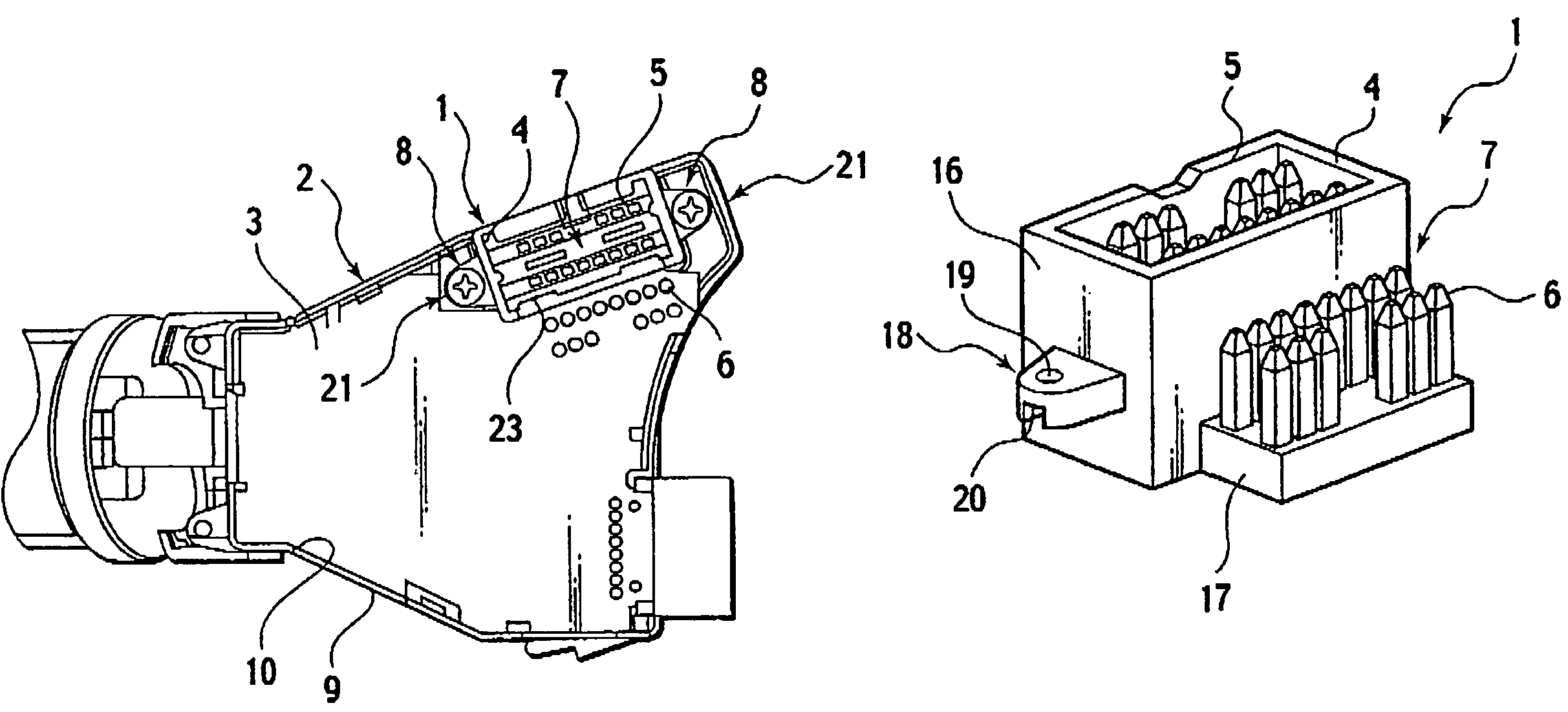
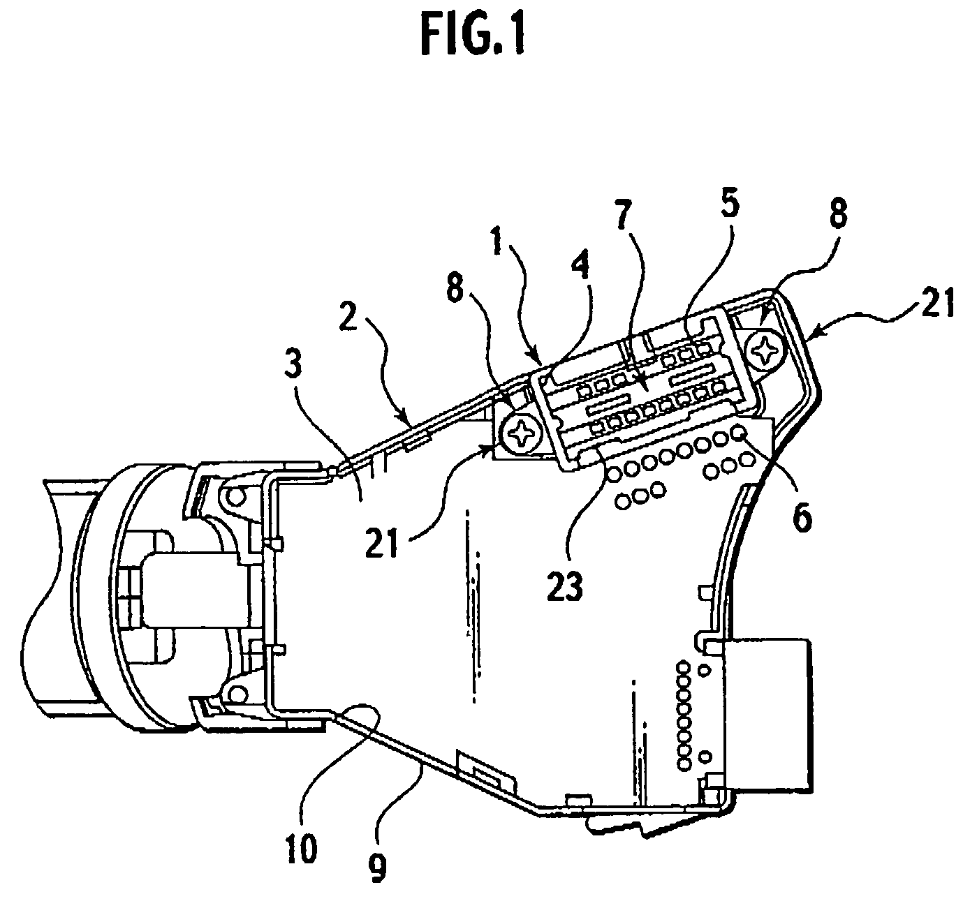
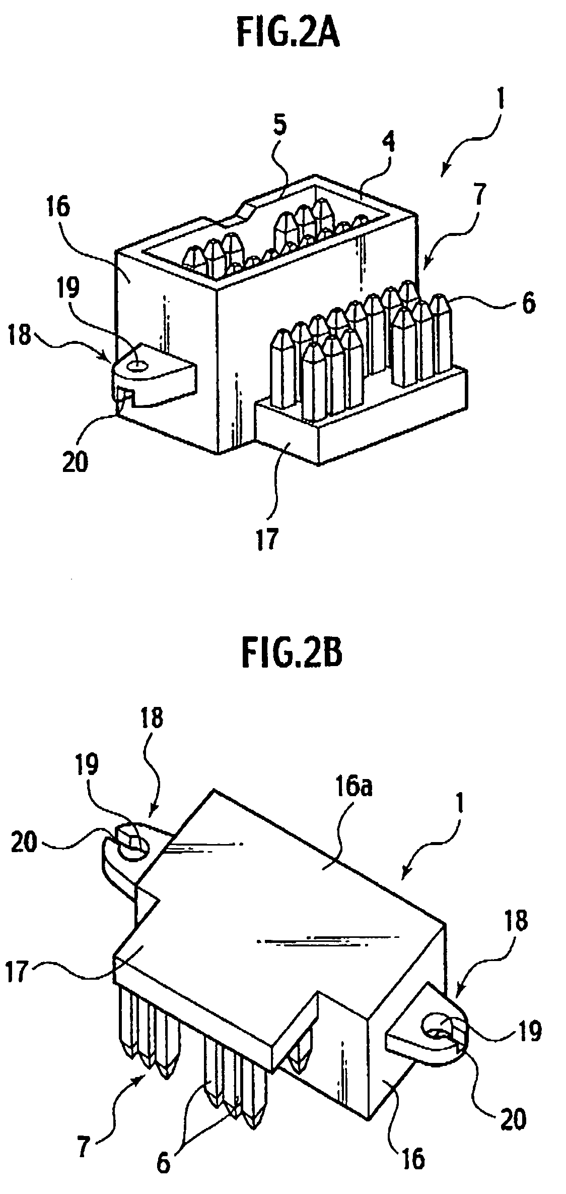
[0027]The circuit board connector having the mounting structure according to the present invention comprises a connector housing for fitting with a mating connector and a terminal which consists of first contactors to be connected to the terminals of the mating connector and second contactors to be conductively connected to the circuit board. The connector housing is anchored in a space closer to the case than the circuit board between the circuit board and the case to screw retaining portions of the case.

[0028]The preferred embodiment will now be described in more detail with reference to attached figures. FIG. 1 is a plan view of a combination switch employing the p...


PUM


Abstract

The mounting structure of the circuit board connector 1 which is conductively connected with a circuit board 3 installed in a case 2 and fixedly mounted to the case 2 comprises a connector housing 4 for joining the circuit board connector 1 with a mating connector, and a terminal 7 including first contactors 5 to be coupled with corresponding terminals of the mating connector and second contractors 6 to be conductively connected to the circuit board 3, wherein the connector housing 4 is located closer the case 2 than the circuit board between the circuit board 3 and the case 2 and fixedly tightened to screw retaining portions 8 of the case.

Description

BACKGROUND OF THE INVENTION[0001]1. Field of the Invention[0002]The present invention relates to a mounting structure of a circuit board connector, which is conductively connected to a circuit board.[0003]2. Description of the Related Art[0004]In general, such a circuit board connector is conductively connected to a circuit board with its housing fixedly mounted directly by screwing to and with one end of its terminal soldered to the circuit board which is then mounted together with the connector to the casing or the like of an apparatus.[0005]While the connector housing is mounted to one side of the circuit board, electronic components are surface mounted on the opposite side of the same for security. Accordingly, when the circuit board is installed in the casing of the apparatus, the connector housing will extend outwardly from the casing thus increasing the overall dimensions.[0006]For overcoming the above drawback, a modification of the connector is disclosed in Japanese Patent ...

Claims


Application Information

Patent Timeline
Patent Type & Authority Patents(United States)
IPC IPC(8): H01R12/00H01R13/66H01R13/74
CPCH01R13/6658H01R13/748H01R12/7047H01R12/716H01R12/724H01R9/16H01R12/00
Inventor KOYASU, RYO
Owner YAZAKI CORP
Learn More