Modular fuel nozzle and method of making

a fuel nozzle and module technology, applied in the direction of burners, liquid spraying apparatus, combustion process, etc., can solve the problems of high manufacturing cost of nozzles of this type, time-consuming and precise completion of machining, drilling and finishing operations, and the inability to meet the requirements of machining and finishing, etc., to achieve cost reduction opportunities, and achieve the effect of reducing the cost of production

Active Publication Date: 2007-07-03
PRATT & WHITNEY CANADA CORP
View PDF161 Cites 36 Cited by
  • Summary
  • Abstract
  • Description
  • Claims
  • Application Information

AI Technical Summary

Problems solved by technology

Nozzles of this type can be costly to manufacture.
However, the machining, drilling and finishing operations still require some time and precision to complete, and hence opportunities for cost-reduction yet exist.

Method used


Image

  • Modular fuel nozzle and method of making
  • Modular fuel nozzle and method of making
  • Modular fuel nozzle and method of making

Examples


Embodiment Construction

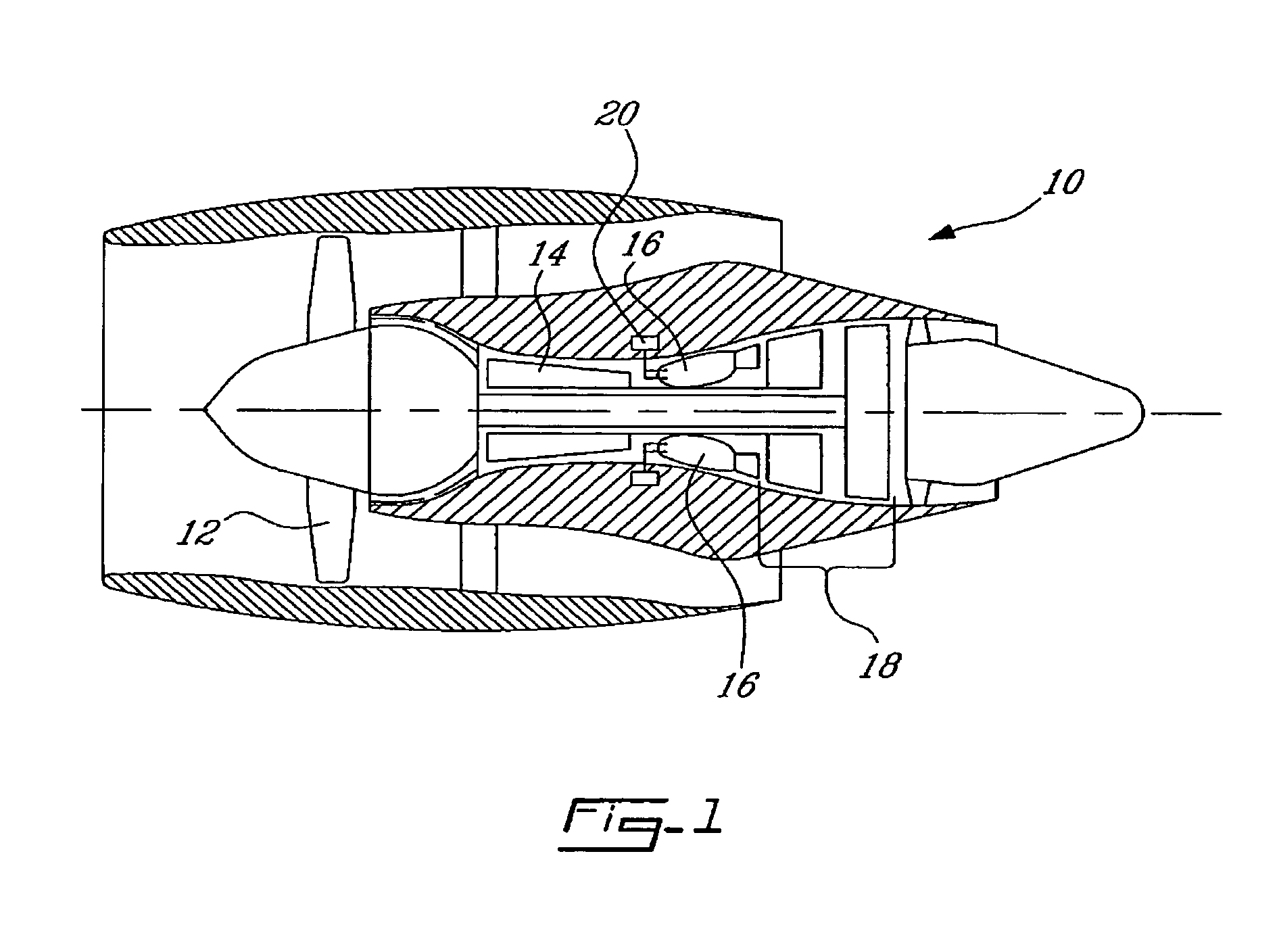
[0021]Referring now to FIG. 1., a turbofan gas turbine engine 10 has in serial flow communication a fan 12 through which ambient air is propelled, a compressor 14 for further pressurizing a portion of the air, a combustor 16 in which the compressed air is mixed with fuel and ignited, and a turbine section 18 for extracting rotational energy from the combustion gases. The combustor 16 includes a plurality of fuel nozzles 20 according to the present invention, as will be now be described in more detail.

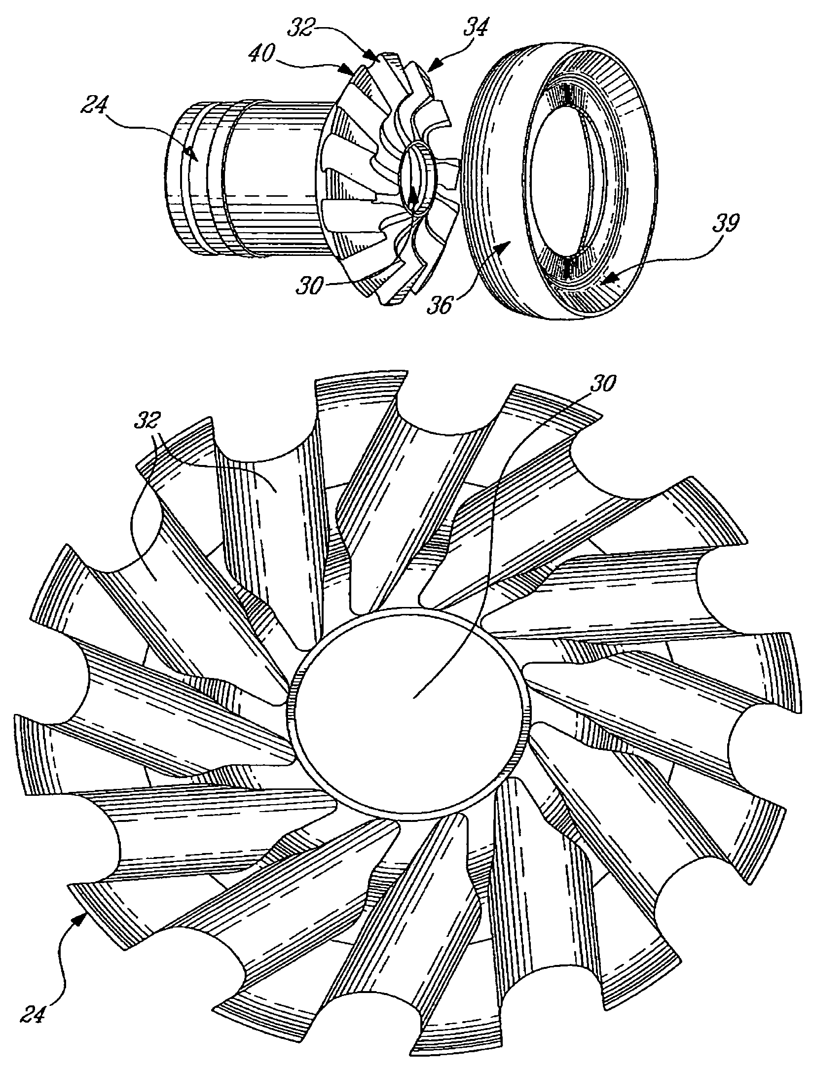
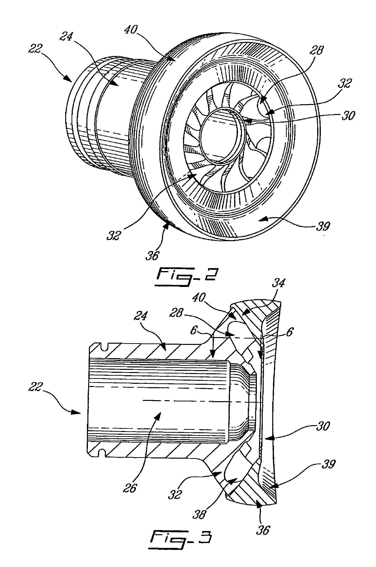
[0022]Referring now to FIGS. 2–5, nozzle 20 includes a nozzle tip 22 which is in this embodiment an air-blast type, meaning that the tip 22 has a body 24, commonly known as a fuel distributor, which has at least a fuel passage 26 defined therethrough, preferably with a fuel swirler 27 therein (not shown, but see FIG. 12), and an array of air passages 28 encircling an spray orifice exit 30 of the fuel passage 26. The fuel swirler 27 may be provided in accordance with the applicant's co-p...


PUM

PropertyMeasurementUnit
angleaaaaaaaaaa
angleaaaaaaaaaa
angleaaaaaaaaaa

Abstract

A modular fuel nozzle configuration is defined which permits lower-cost manufacturing operations such as injection moulding to be employed. Also described is a method of making such a component.

Description

TECHNICAL FIELD[0001]The technical field of the invention relates to fuel nozzles such as those for use in gas turbine engines, and in particular fuel nozzles which employ pressurized air.BACKGROUND OF THE ART[0002]Fuel nozzles vary greatly in design. One approach, shown in U.S. Pat. No. 5,115,634, involves the use of swirler airfoils or vanes arrayed around a central fuel orifice. Nozzles of this type can be costly to manufacture. Another approach, shown in the Applicant's U.S. Pat. No. 6,082,113 provides a plurality or air channels drilled around a central fuel orifice in a solid nozzle tip, which provides good mixing and is relatively cheaper to manufacture. However, the machining, drilling and finishing operations still require some time and precision to complete, and hence opportunities for cost-reduction yet exist.SUMMARY OF THE INVENTION[0003]In one aspect, the present invention provides a fuel nozzle for a gas turbine engine, in nozzle comprising a body defining at least a c...

Claims


Application Information

Patent Timeline
Patent Type & Authority Patents(United States)
IPC IPC(8): B05B7/10B05B7/06
CPCF23D11/107F23D11/383F23R3/28Y10T29/49405F23R2900/00018Y10T29/49426Y10T29/49432F23R2900/00017
Inventor PROCIW, LEV ALEXANDERBRAND, JOSEPH HORACE
Owner PRATT & WHITNEY CANADA CORP
Why Eureka
Try Eureka