Optical fiber splice case

a technology of optical fiber and enclosure assembly, which is applied in the direction of optics, optical light guides, instruments, etc., can solve the problems of inconvenient use, preventing the enclosure from being readily adaptable, and signal passing through the enclosure has the potential to be disturbed

Active Publication Date: 2007-07-03
PREFORMED LINE PROD CO
View PDF94 Cites 102 Cited by
  • Summary
  • Abstract
  • Description
  • Claims
  • Application Information

AI Technical Summary

Problems solved by technology

These prior enclosures are satisfactory to a greater or lesser degree but often have certain defects which make them inconvenient to use or prevent them from being readily adaptable to changing environments and conditions.
While performing these tasks, any signals passing through the enclosure have the potential to be disturbed.

Method used


Image

  • Optical fiber splice case
  • Optical fiber splice case
  • Optical fiber splice case

Examples


Embodiment Construction

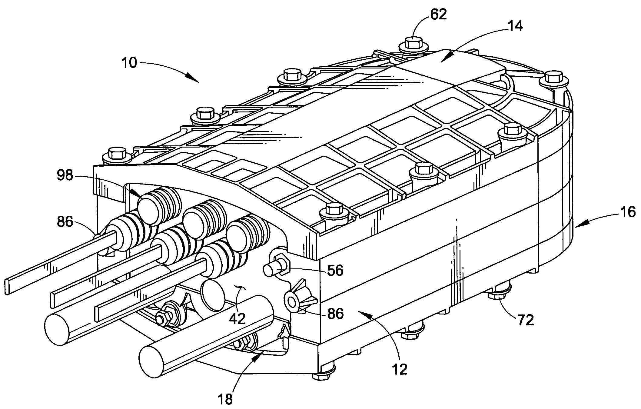
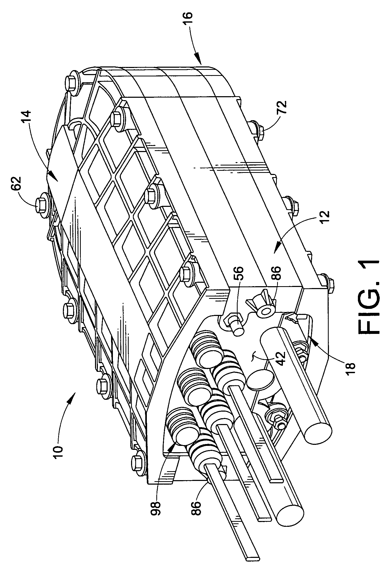
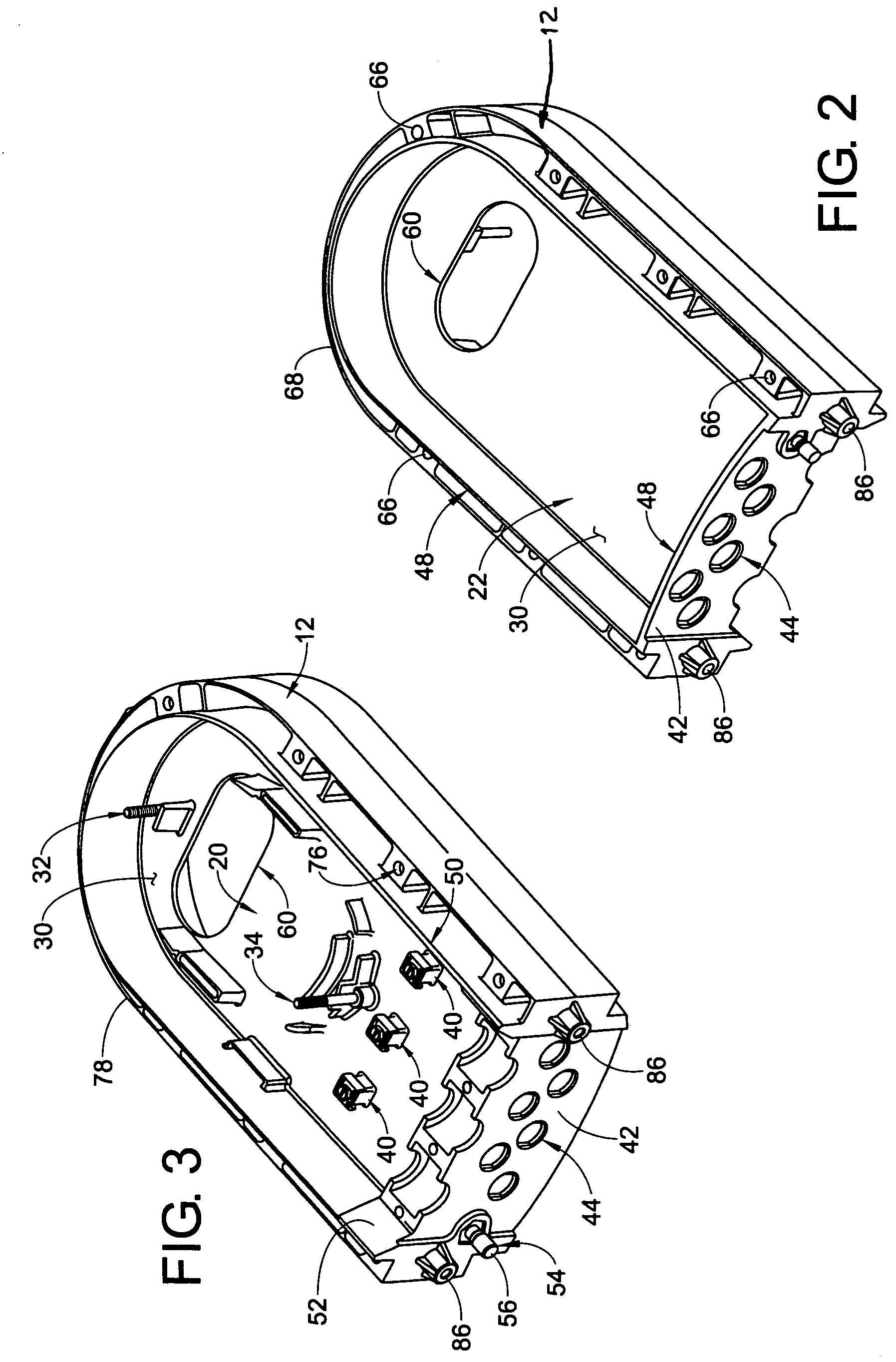
[0037]Referring now to the drawings wherein the showings are for the purposes of illustrating exemplary embodiments of the invention only and not for purposes of limiting same, the overall construction of the subject optical fiber splice case (housing) assembly 10 can best be understood by reference to FIGS. 1 through 5. As illustrated therein, the splice case assembly 10 comprises an enclosure base 12, enclosure covers 14, 16, and an end plate 18 that houses and encloses a splice chamber or splice tray support area 20 and a drop chamber or fiber jumper storage compartment 22 as shown. The housing assembly 10 formed by the pair of cover members 14, 16, enclosure base 12, and the end plate 18 are joined together in a sealed clamping relationship to define a flat truncated oval-shaped splice case and volume area therein (FIG. 1).

[0038]FIG. 1 displays the splice case assembly 10. The central element of the assembly 10 is the enclosure base 12. The enclosure base 12 is a double-sided el...


PUM


Abstract

An optical fiber splice case particularly adapted for providing fiber optic links directly to a home, business, et al. is provided wherein an enclosure base has a dividing wall defining a drop chamber on a first side of the wall and a splicing chamber on a second side of the wall. A first and a second cover member is selectively sealingly engaged with opposing sides of the enclosure base. The enclosure base includes a bulkhead member having a plurality of optical fiber ports therethrough.

Description

[0001]This application claims the benefit of U.S. Provisional Application Ser. No. 60 / 616,310 filed Oct. 6, 2004 which in turn claims the benefit of U.S. Provisional Application Ser. No. 60 / 508,962, filed Oct. 6, 2003.CROSS REFERENCE TO RELATED PATENTS AND APPLICATIONS[0002]The present application is related to U.S. patent application Ser. No. 11 / 126,740 filed May 11, 2005 entitled Convertible Fiber Closure Platform which in turn claims the benefit of U.S. Provisional Application Ser. No. 60 / 569,910 filed May 11, 2004, the disclosures of which are incorporated herein by reference in their entirety.BACKGROUND OF THE INVENTION[0003]The subject invention is directed to a waterproof and airtight cable splice enclosure assembly. Assemblies of the type under consideration are particularly suited for enclosing and housing fiber optic cables such as loose buffer and unitube type cables and will be described with particular reference thereto. However, the apparatus could equally well be used...

Claims


Application Information

Patent Timeline
Patent Type & Authority Patents(United States)
IPC IPC(8): G02B6/00
CPCG02B6/4442G02B6/4444G02B6/44465G02B6/44775
Inventor GRUBISH, CHRISTOPHERMILLER, KEITH A.WHAPHAM, ROBERTWITGEN, LUKEHOFSTETTER, JOHN
Owner PREFORMED LINE PROD CO
Why Eureka
Try Eureka