Light distribution control device

a control device and light technology, applied in the direction of lighting support devices, fixed installations, lighting and heating equipment, etc., can solve the problem of large size of the entire vehicular lighting fixtur

Inactive Publication Date: 2007-07-10
HITACHI LTD
View PDF10 Cites 103 Cited by
  • Summary
  • Abstract
  • Description
  • Claims
  • Application Information

AI Technical Summary

Benefits of technology

[0005]An object of the present invention is to provide a vehicular lighting fixture for the AFS which can set a lot of light distribution patterns with few illuminants, that is, without making the entire lighting fixture larger.
[0013]The present invention can realize a vehicular lighting fixture for the AFS which can set a lot of light distribution patterns without making the entire lighting fixture larger by not only blinking or modulating light from a plurality of illuminants with different light distribution, but also changing the optical axis by moving each of illuminants or each of reflectors which reflects the light irradiated from the illuminants independently.

Problems solved by technology

However, the following problems exist in the above-mentioned prior art.
Therefore, the problem that a lot of illuminants are needed to increase the light distribution patterns to be set, and the entire vehicular lighting fixture becomes large exists.

Method used


Image

  • Light distribution control device
  • Light distribution control device
  • Light distribution control device

Examples


embodiment 1

[Embodiment 1]

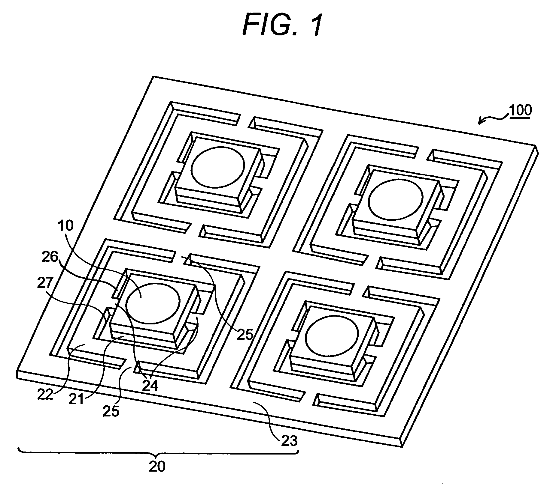
[0026]Embodiment 1 of the present invention will be explained by referring to FIG. 1. Vehicular lighting fixture 100 in FIG. 1 is rectangular, and it is made by using planar seat 20. A plurality of illuminants 10 are arranged on movable substrate 21 of seat 20. Seat 20 comprises a plurality of movable substrates 21, a plurality of inner frames 22, an outer frame 23, a plurality of beams 24 which link movable substrate 21 to inner frame 22, and a plurality of beams 25 which link inner frame 22 to outer frame 23. Two through holes 26 and 27 are arranged in a rectangular shape to outer frame 23 as shown in the figure. As a result, inner frame 22 and movable substrate 21 are supported to outer frame 23 by beams 24 and 25. Beam 24 and beam 25 are arranged in a crosswise direction. That is, they are arranged in an orthogonal direction.

[0027]The axis of the beam by which movable substrate 21 and inner frame 22 are linked and the axis of the beam by which inner frame 22 and ou...

embodiment 2

[Embodiment 2]

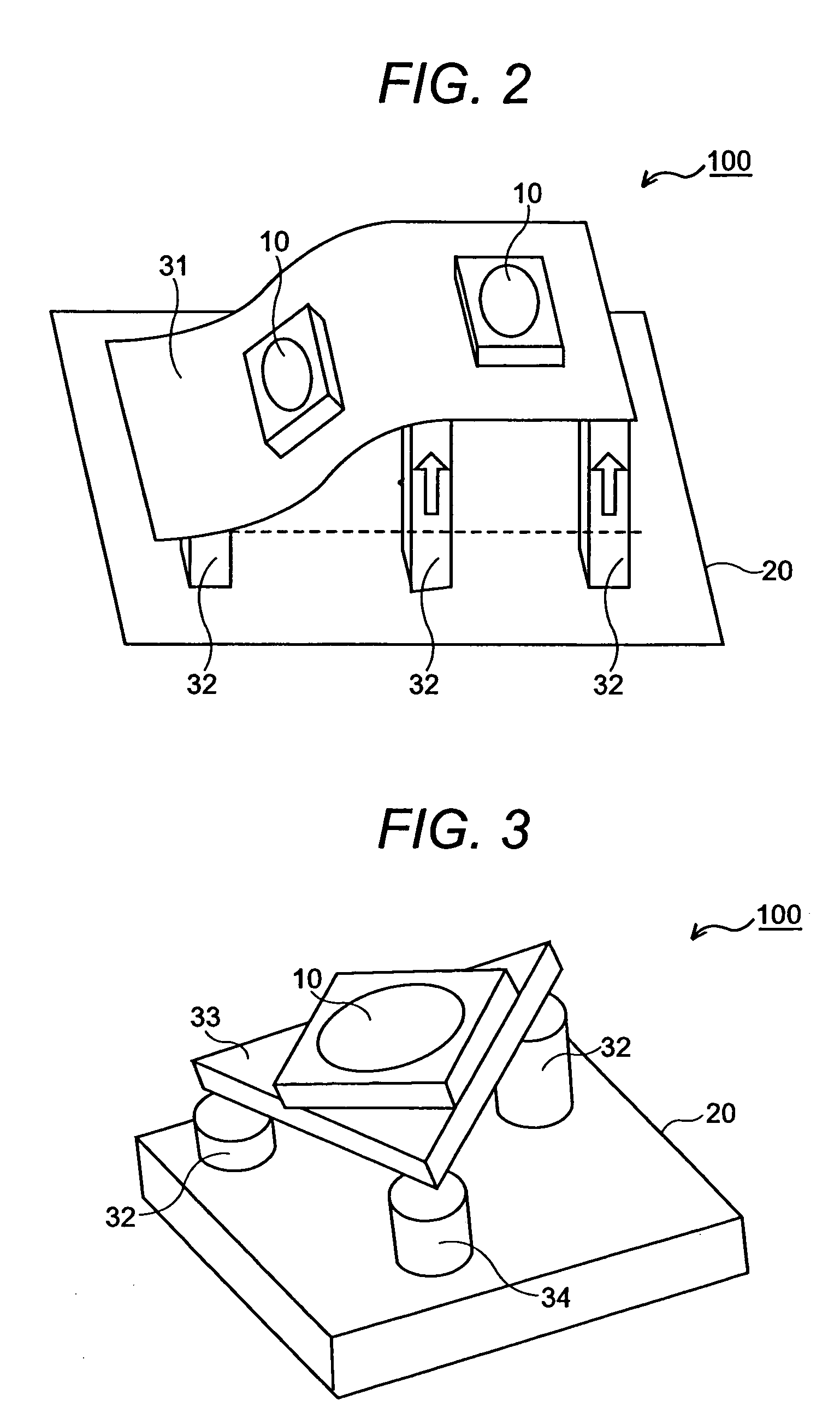
[0030]Embodiment 2 of the present invention will be explained by referring to FIG. 2. Like numerals designate like members to avoid the duplicated explanation. Illuminant 10 is mounted on deformable type substrate 31 which provides on seat 20, and deformable type substrate 31 is supported by a plurality of extendable support members 32. Deformable type substrate 31 is transformed by expanding or contracting a plurality of extendable support members 32 independently. Setting the arbitrary light distribution pattern becomes possible by changing the optical axis of illuminant 10 mounted on deformable type substrate 31 according to such transformation.

[0031]Although deformable type substrate 31 is transformed with extendable support members 32 in this embodiment, it is also possible to transform deformable type substrate 31 by using cams or rollers. Moreover, deformable type substrate 31 may be transformed by using non-contact force like electrostatic force and electromagn...

embodiment 3

[Embodiment 3]

[0032]Embodiment 3 of the present invention will be explained with reference to FIG. 3. Illuminant 10 is mounted on rigid substrate 33 provided on seat 20, and rigid substrate 33 is supported by a plurality of extendable support members 32. Rigid substrate 33 is inclined by expanding or contracting a plurality of extendable support members 32 independently. Setting the arbitrary light distribution pattern becomes possible by changing the optical axis of illuminant 10 mounted on rigid substrate 33 by this inclination.

[0033]Although rigid substrate 33 is inclined with extendable support members 32 in this embodiment, it is also possible to incline rigid substrate 33 by using cams or rollers. Moreover, rigid substrate 33 may be inclined by using non-contact force like electrostatic force and electromagnetic force, etc.


PUM


Abstract

In this light distribution control device in order to provide a vehicular lighting fixture for an Adaptive Frontlighting System (AFS) in which a lot of light distribution patterns can be set without making the entire lighting fixture larger, beams which link said movable substrates to said inner frames and beams which link said inner frames to said outer frame are mutually orthogonal, and a light distribution pattern is set by deforming under torsion the beams which link said movable substrates to said inner frames and the beams which link said inner frames to said outer frame, and swinging each of said movable substrates with respect to said outer frame in the biaxial directions independently.

Description

BACKGROUND OF THE INVENTION[0001]The present invention relates to a vehicular lighting fixture for an Adaptive Frontlighing System (AFS), which can control the light distribution.[0002]For instance, there is Japanese Patent Application Laid-Open No. 2004-71409 as a well-known technology relevant to such a vehicular lighting fixture for the AFS which can control the light distribution.[0003]In the vehicular lighting fixture for the AFS which can control the light distribution described in Japanese Patent Application Laid-Open No. 2004-71409, a plurality of illuminants with different light distribution is provided, and light distribution is controlled by blinking those illuminants or adjusting the quantity of light of those illuminants.BRIEF SUMMARY OF THE INVENTION[0004]However, the following problems exist in the above-mentioned prior art. That is, in the vehicular lighting fixture for the AFS which can control light distribution described in Japanese Patent Application Laid-Open No...

Claims


Application Information

Patent Timeline
Patent Type & Authority Patents(United States)
IPC IPC(8): B60Q1/06F21S8/10F21V14/02
CPCB60Q1/08F21S41/675
Inventor NANIWA, IRIZOSATOU, KAZUTAKAHORINO, MASAYAMONJI, TATSUHIKOOHSUMI, KEN
Owner HITACHI LTD
Why Eureka
Try Eureka