Method for assigning control channels

a control channel and channel technology, applied in the field of electrical interconnection, can solve the problems of stalling of the ‘mini and ‘micro’ coaxial wiring/rf radio industry, difficult manufacturing, and inability to achieve ideal performance in many rf design areas

Active Publication Date: 2009-06-25
ZEBRA TECH CORP
View PDF11 Cites 74 Cited by
  • Summary
  • Abstract
  • Description
  • Claims
  • Application Information

AI Technical Summary

Problems solved by technology

The current method of RF wiring in today‘s’ personal computers, cell phones, and tablet PCs—although continually improved by companies around the world, still remains with many problems in design, difficulty of manufacture, non-ideal performance in many RF design areas.
The entire WiFi and WWAN world has gradually, incrementally, improved many of these areas, including RF connector and coaxial wire design, but several problem areas still remain.
Additionally, the ‘mini and ‘micro’ coaxial wiring / RF radio industry seems to be stalled in a paradigm of what wire is currently used, and how the antennas are supplied—commonly with wire ‘tails’.
Moreover, when one enters the world of Tablet PCs, the design and manufacturing problems, errors get even more numerous.
The routing is not optimal and require being handled multiple times as parts are added.
Some of these connections such as WWAN Main and WWAN Auxiliary connections must be routed outside the devices EMI shield 18 because the shielding of even the better quality prior art 1.32 / 1.37 mm Micro-wire coaxial cable is inadequate to protect the devices circuitry from the WWAN signals coursing trough the micro-wire.
Even the connectors may not be attached in a uniform manner.
When the wire is pinched VSWR performance is compromised causing signal reflection, waste and detuning of the cable).
Thus more care is required in the manufacture and repair of products using the wire and thus in the design in the product resulting in design limitations caused by using the micro-wire.
New EMI regulatory specifications have made it more difficult to comply with wireless noise specifications EMI Noise couples into coaxial wires to varying degrees requiring thinner micro-wire.
For WWAN cell phone TIS EMI testing, this poor performance frequently requires additional external shielding to further shielding U / FL wire.
For WWAN cell phone TIS EMI testing, this poor performance also frequently requires additional external shielding to boost shielding effectiveness of U / FL wire.
Because many wireless devices today require multiple antennas, multiple wires with are required frequently resulting in haphazard and varied placement of both antennas and wires which each must be individually routed and clipped in place taking many time consuming assembly steps.
The more steps the greater the chance of error during assembly or repair.
Mounting mechanisms being much too close to the signal inside the wire is both unavoidable and undesirable to performance.
Another design limitation related to the Micro wire relates to its minimum bend radius.
Dropping below this radius will cause the cable to kink resulting in the aforementioned performance degradation of the cable.
To violate this spec is to essentially, again, ‘kink’ the antenna wire leading to VSWR and performance losses.
Because of the problems associated with the micro-wire cable routing, currently it is atypical to provide a service loop in the RF wire making assembly and repair of the system more difficult.
Typically when a service loop is provided it roams into EMI problematic areas requiring additional cable EMI and routing management.
A service loop is potentially even more problematic if the service loop enters the actual antenna resonating area(s), affecting or detuning performance.
It is difficult to service, repair or upgrade these components and frequently requires disassembling of the entire device.
Furthermore, dedicated, non-swappable antennas typical in this industry require longer test periods to have multiple systems and tests support permutations of antennas and radio technology.

Method used


Image

  • Method for assigning control channels
  • Method for assigning control channels
  • Method for assigning control channels

Examples


Embodiment Construction

[0051]Preferred embodiments of the present invention are illustrated in the FIGUREs, like numerals being used to refer to like and corresponding parts of the various drawings.

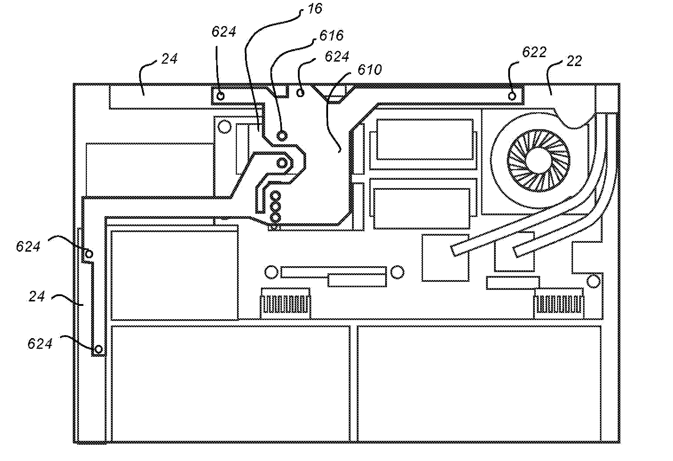
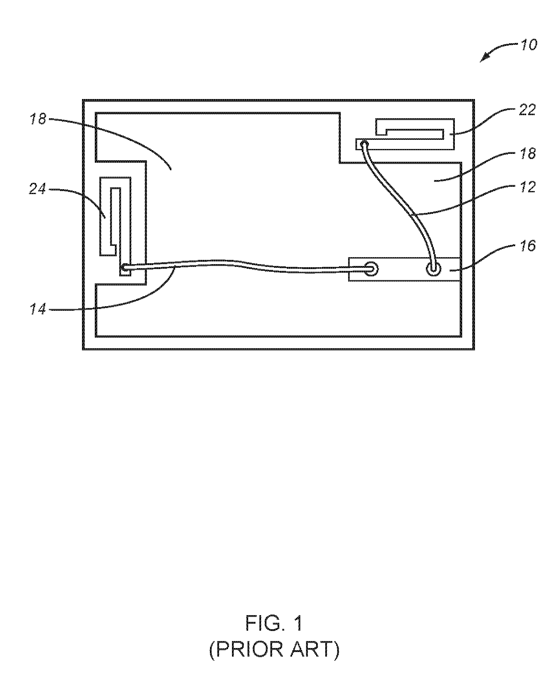
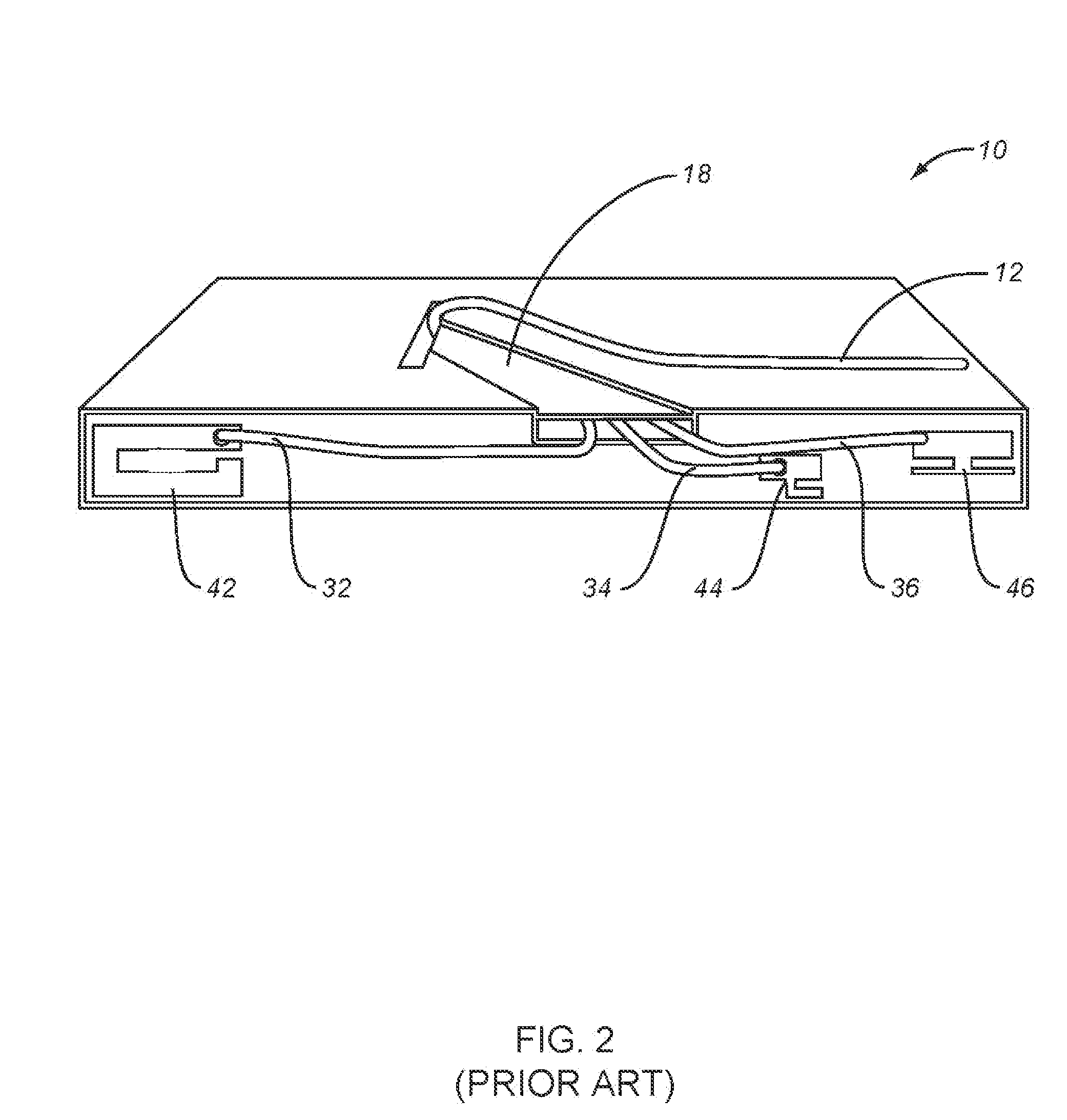
[0052]The present invention generally relates to connecting wireless transmitter and / or receiver components electronic devices. For this purpose the invention employs the use of flexible circuit boards—particularly flexible printed circuits (FPC) technology. Devices with prior art micro-wire connections were discussed above in regards to FIG. 1, FIG. 2, FIG. 3, FIG. 4 and FIG. 5. Typical micro-wires have a diameter of approximately 1.37 mm (54 mil). Using FPCs the applicants have made connectors which are less than 0.50 mm (20 mils) in thickness which are drastically less susceptible to kinking, crushing, crimping or other hazards mentioned above.

[0053]FIG. 6 illustrates a simple embodiment of an FPC RF electrical connector 100 according to the present invention. It is comprised of the FPC section 110 and two s...


PUM


Abstract

The present invention is a mobile device capable of transmitting or receiving wireless signals and incorporating an FPC shielded RF signal conductor for connecting transmitter and/or receiver circuitry to an associated RF antenna or antennas. In some embodiments FCP may incorporate the antenna in an unshielded section of the FPC. In some embodiments a single FPC may provide for multiple RF carrier conductors each with their own associated shielding.

Description

RELATED APPLICATION[0001]This application is a Utility application claiming priority of provisional application Ser. No. 60 / 999,906 filed on Oct. 22, 2007.TECHNICAL FIELD OF THE INVENTION[0002]The present invention generally relates to electrical interconnection of electromagnetic wireless transmitters and receivers to the antennas which transmit and / or receive electromagnetic wireless signals. More particularly this invention particularly relates to and is particularly useful to such interconnections in mobile devices such as mobile computers, radios, mobile phones, personal assistant devices (PDAs) or any other device which either transmits or receives wireless electromagnetic signals of one or multiple radio frequency (RF) or technologies with one or multiple wireless antennas.BACKGROUND OF THE INVENTION[0003]The current method of RF wiring in today‘s’ personal computers, cell phones, and tablet PCs—although continually improved by companies around the world, still remains with m...

Claims


Application Information

Patent Timeline
Patent Type & Authority Applications(United States)
IPC IPC(8): H04B1/38
CPCH05K1/0219H05K1/0298H05K1/0393H05K1/189H05K2201/10189H05K2201/09709H05K2201/09809H05K2201/09981H05K2201/09618
Inventor STEIGERWALD, TODDBENTLEY, TOMMAYFIELD, JERRYVIER, BRAD
Owner ZEBRA TECH CORP
Why Eureka
Try Eureka