Linking zones for object tracking and camera handoff

a technology for object tracking and camera handoff, applied in the field of video surveillance, can solve the problems of object tracking becoming more difficult, affecting the effect of camera handoff, and affecting the reappearance of targets in time and/or space, so as to facilitate camera handoff facilitate camera handoff

Active Publication Date: 2007-07-10
COLUMBIA PEAK VENTURES LLC
View PDF7 Cites 82 Cited by
  • Summary
  • Abstract
  • Description
  • Claims
  • Application Information

AI Technical Summary

Benefits of technology

This patent describes a way to switch cameras without having to calibrate them first in a multi-camera surveillance system. The technique uses connected areas called "linked zones" to track moving objects across different cameras. By monitoring these zones, it becomes easier to find and follow new objects as they move around. Overall, this approach makes it simpler and faster to install and use multiple cameras in various settings.

Problems solved by technology

The technical problem addressed in this patent is how to effectively track multiple objects as they move within a surveillance system, particularly when they appear and disappear in different cameras' fields of view. Existing techniques such as prediction and mapping have been developed to address this problem, but they may not always be reliable or efficient. The patent proposes a new approach to improve the accuracy and reliability of object-tracking in surveillance systems.

Method used


Image

  • Linking zones for object tracking and camera handoff
  • Linking zones for object tracking and camera handoff
  • Linking zones for object tracking and camera handoff

Examples


Embodiment Construction

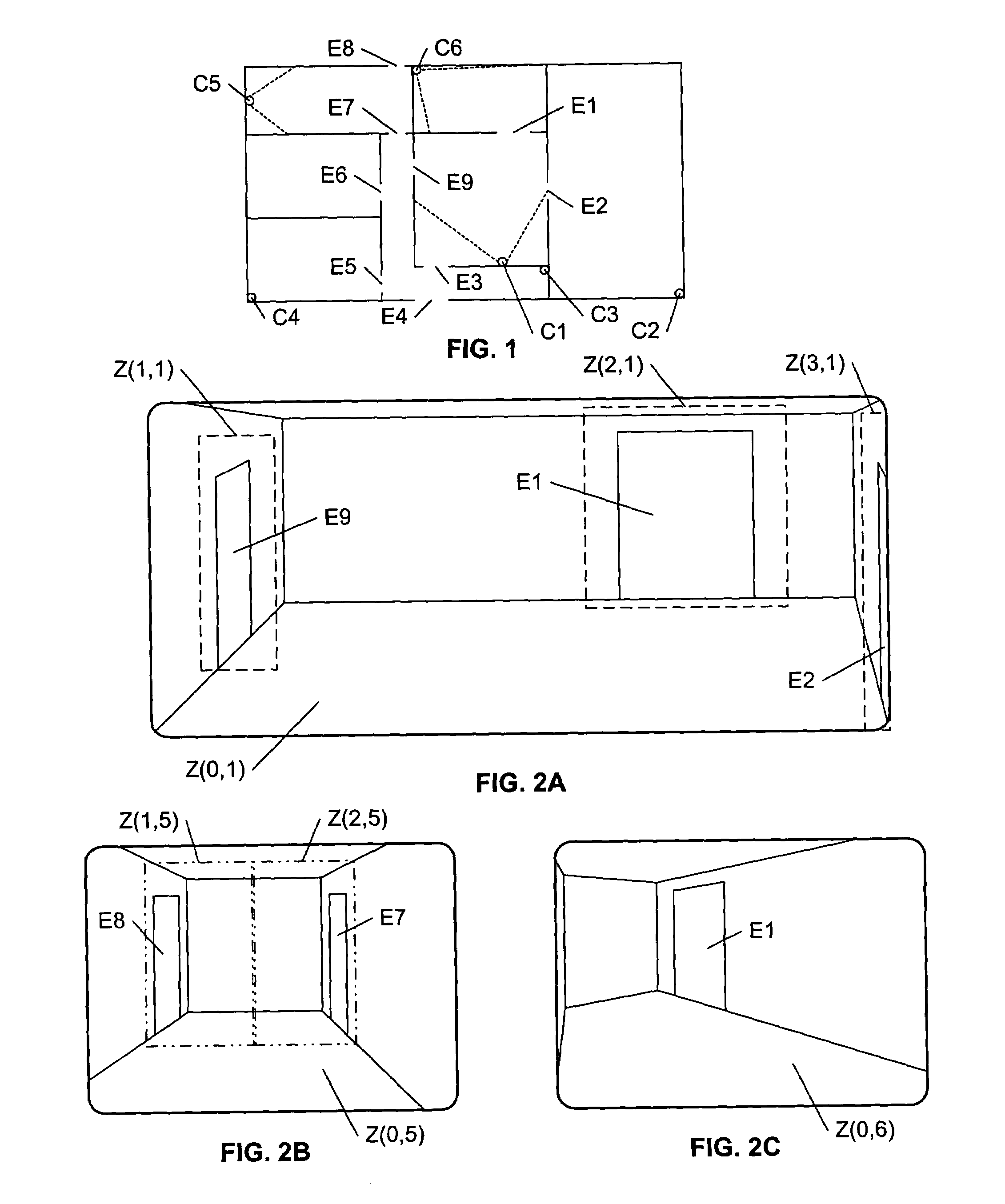
[0018]FIG. 1 illustrates an example floorplan of a multiple-camera surveillance area. The floorplan illustrates areas connected by egresses E1–E9 Disposed about the surveillance area are cameras C1–C6. The field of view of two of the cameras, C1 and C5, are illustrated as dashed lines on the floorplan.

[0019]Any of a variety of techniques can be used to track one or more objects within a field of view of a camera. As an object traverses the camera's field of view, an object-tracking module searches each sequential image frame for the target, based on the appearance and / or the motion pattern of the target within a prior image frame. The appearance of the target in each sequential frame will not generally be identical to its appearance in the prior frame, due to changes in the object's posture and orientation as it moves, or due to changes in lighting conditions, camera angle, as the object enters different areas, and so on. Generally, the amount of change from frame to frame is limite...


PUM


Abstract

Linked zones define the temporal and spatial relationships among multiple zones of a surveillance area, and are used to model an object's disappearance from one zone, for potential reappearance at another zone. One or more zones are defined within each camera's field of view. Two zones are linked if an object that disappears from one zone is capable of appearing in the other zone. Each link has an associated delay parameter or function that characterizes the time delay, if any, between a disappearance and subsequent appearance. For each zone, a set of other zones that are linked to this zone is maintained. When an object disappears from a zone, the set of other zones that are linked to this zone is used to reduce the search space for object appearances corresponding to this disappearance. When the corresponding object appearance is found, the tracking function is handed-off to the tracking module associated with the zone in which the object appeared.

Description


Claims


Application Information

Patent Timeline
Owner COLUMBIA PEAK VENTURES LLC
Why Eureka
Try Eureka