Resonant converters and control methods thereof

a technology of resonant converters and control methods, applied in the direction of electric variable regulation, process and machine control, instruments, etc., can solve the problems of resonant converters, driving and magnetic component losses, and general view of variable switching frequency control as drawbacks, so as to improve reduce the switching frequency range. , the effect of improving the performance of resonant converters

Active Publication Date: 2015-08-13
DELTA ELECTRONICS INC
View PDF16 Cites 134 Cited by
  • Summary
  • Abstract
  • Description
  • Claims
  • Application Information

AI Technical Summary

Benefits of technology

[0012]The present invention provides control methods for resonant converters that offer improved performance. Specifically, the control methods of the present invention provide improved performance in resonant converters that operate with a wide input-voltage range or a wide output-voltage range (or both) by substantially reducing the switching-frequency range. Reduction in the switching frequency range is achieved by controlling the output voltage with a combination of variable-frequency control and time-delay control. According to one embodiment of the present invention, variable-frequency control may be used to control the primary switches of an isolated resonant converter, while delay-time control may be used to control secondary-side rectifier switches provid

Problems solved by technology

Variable switching-frequency control is generally seen as a drawback of a resonant converter, especially in an application with a wide input voltage range or a wide output voltage range.
Specifically, as the input or output voltage range increases, the control frequency range also increases, so that driving and magnetic component losses also increase, thereby reducing conversion efficiency.
Furthermore, in many applications, the converter is restricted to operate within a relatively limited frequency range to avoid interfering with other parts of the system.
While a resonant converter can operate with a constant frequency (i.e., in a “clamp-mode” operation), such an operation is not desirable because the increased

Method used


Image

  • Resonant converters and control methods thereof
  • Resonant converters and control methods thereof
  • Resonant converters and control methods thereof

Examples


Embodiment Construction

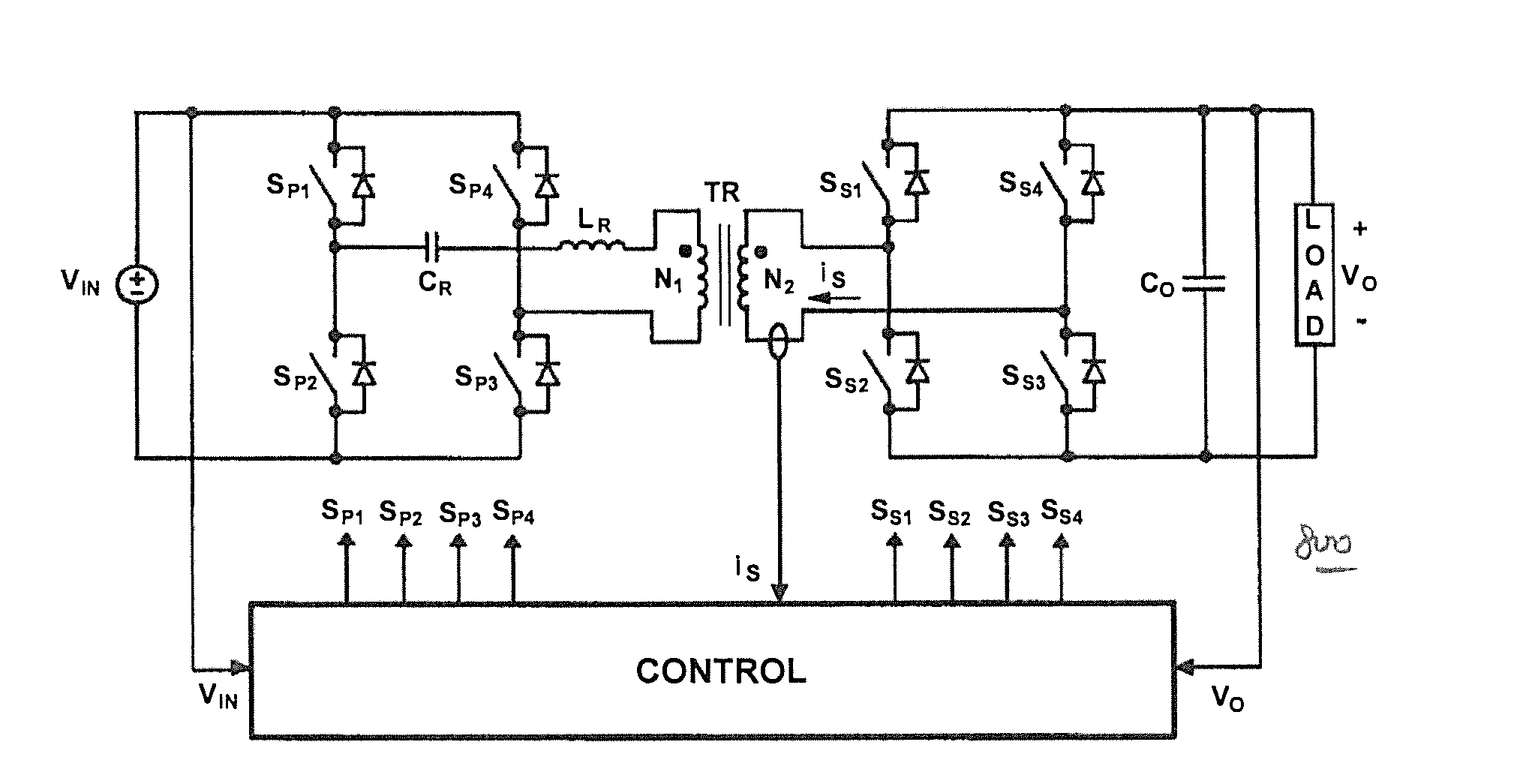
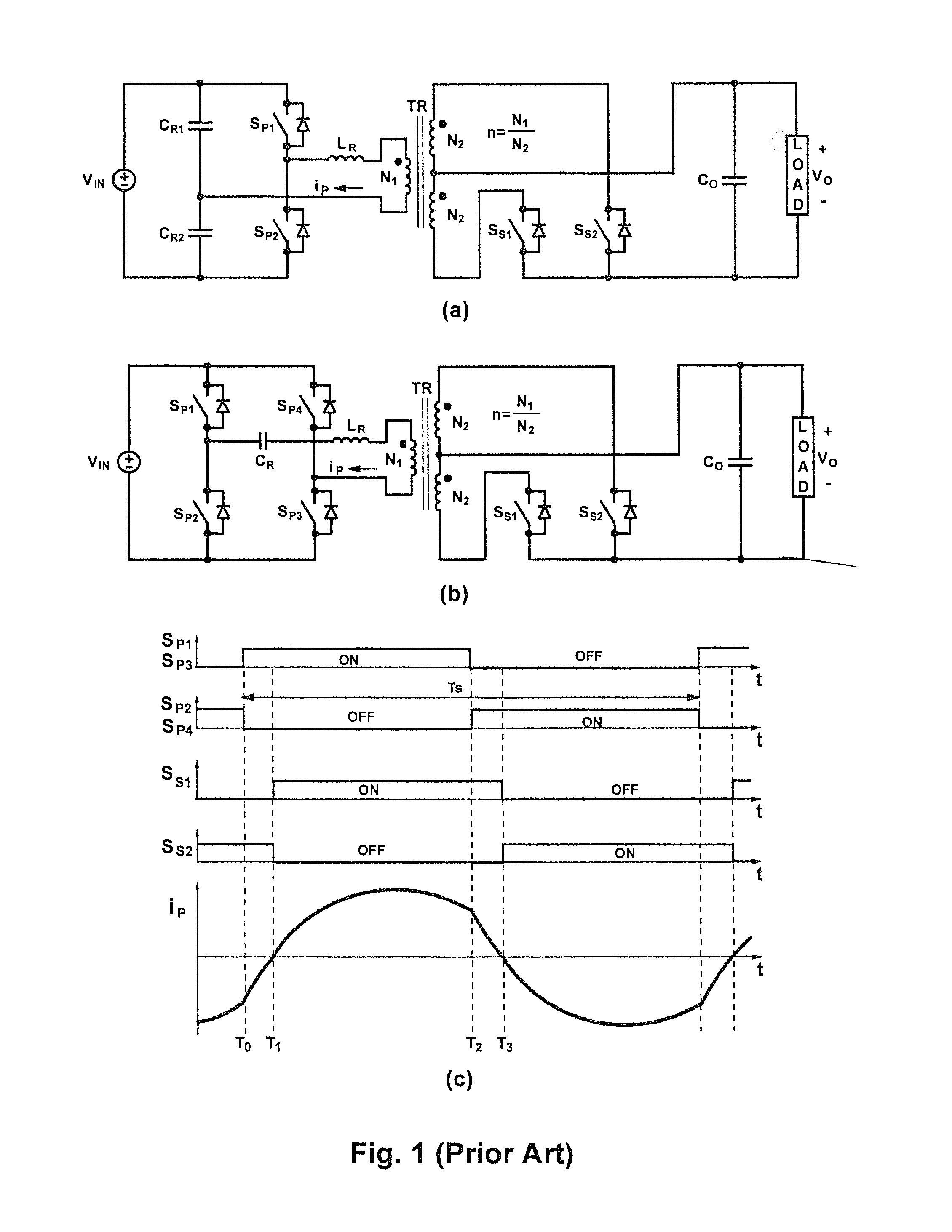
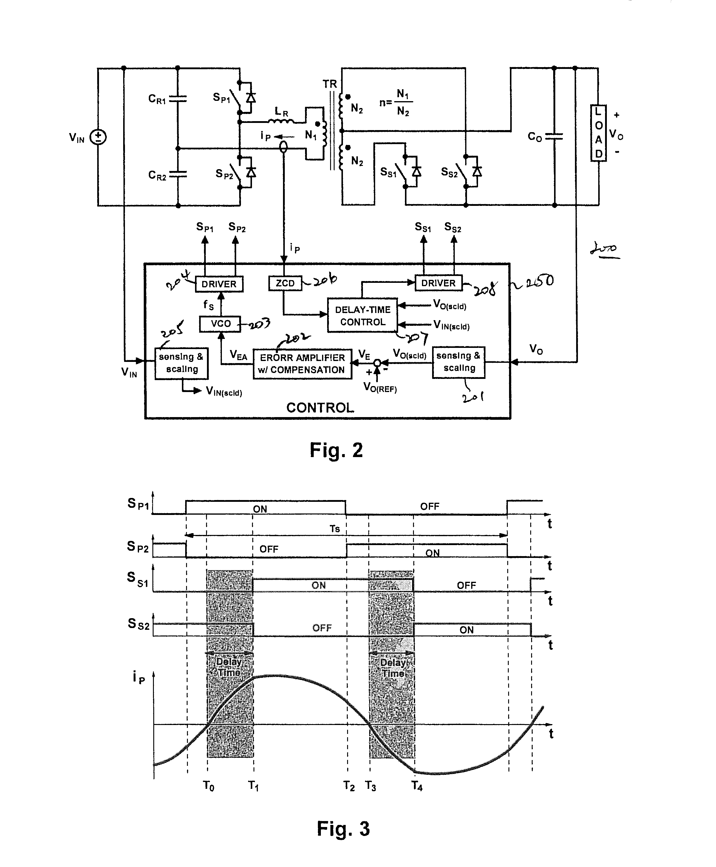
[0034]FIG. 2 illustrates a control method in isolated half-bridge series-resonant converter 200 with a center-tap secondary winding in transformer TR, according to one exemplary embodiment of the present invention. (Except for its control circuit, half-bridge series resonant converter 200 has the same topology as the half-bridge resonant converter of FIG. 1(a)). As shown in FIG. 2, the half-bridge series-resonant converter 200 uses an isolation transformer TR with a center-tapped secondary winding. The primary side of the converter includes switches SP1 and SP2, resonant capacitors CR1 and CR2, and resonant inductor LR. The secondary side of the resonant converter includes switches SS1 and SS2 and output or filter capacitor CO, which is coupled across the load. Alternatively, filter capacitor CO may be coupled to the load through a second-stage LC filter. Even when present, the second-stage LC filter does not substantively affect the control method of the present invention. Accordin...


PUM


Abstract

Control methods for resonant converters offer improved performance in resonant converters that operate with a wide input-voltage range or a wide output-voltage range (or both) by substantially reducing the switching-frequency range. Reduction in the switching frequency range is achieved by controlling the output voltage with a combination of variable-frequency control and time-delay control. Variable-frequency control may be used to control the primary switches of an isolated resonant converter, while delay-time control may be used to control secondary-side rectifier switches provided in place of diode rectifiers. The secondary-side control may be implemented by sensing the secondary current or the primary current (or both) and by delaying the turning-off of the corresponding secondary switch with respect to the zero crossings in the secondary current or the primary current.

Description

BACKGROUND OF THE INVENTION[0001]1. Field of the Invention[0002]The present invention relates to control methods used in resonant converters. More particularly, the present invention relates to individual converter control and paralleled resonant converters with active current-sharing control.[0003]2. Description of the Prior Art[0004]Generally, a resonant converter uses a resonant-tank circuit to shape switch voltages or current waveforms, or both, to minimize switching losses and to allow high-frequency operations without compromising conversion efficiency. Resonant converters are therefore extensively used in state-of-the-art power supplies that offer the highest power densities and efficiencies. Resonant converters are also preferred as power supply circuits for medical applications because of their superior electromagnetic interference (EMI) performance relative to their “hard”-switched counterparts. As resonant converters absorb component parasitics into their resonant-tank ci...

Claims


Application Information

Patent Timeline
IPC IPC(8): H02M3/335H02M1/00
CPCH02M3/33546H02M3/33592H02M3/285Y02B70/10H02M1/0058H02M1/0043H02M3/33571H02M3/33573H02M3/01H02M1/0085
Inventor JANG, YUNGTAEKJOVANOVIC, MILAN M.
Owner DELTA ELECTRONICS INC
Why Eureka
Try Eureka