Ultrawide-band communication system and method

a communication system and ultra-wideband technology, applied in the field of communication, can solve the problems of low power consumption, channelization and cost, reuse of available resources, etc., and achieve the effects of reducing distortion, increasing bandwidth, and adding fidelity

Inactive Publication Date: 2005-01-25
TDC ACQUISITION HLDG
View PDF3 Cites 134 Cited by
  • Summary
  • Abstract
  • Description
  • Claims
  • Application Information

AI Technical Summary

Benefits of technology

The effect of using the cross correlation function for the modulation transfer function is to cause the output of the receiver to be a non-linear function of the amplitude of the input. For baseband modulation, this is undesirable. However, for subcarriers, such as FM, AM, FSK, PSK and Manchester, the harmonics are filtered thereby eliminating any distortion. Such filtering can not remove harmonics when baseband modulation is used, because the harmonics stay at baseband, and thus the signal is irrecoverable.
The addition of subcarriers also provides added fidelity in the form of more bandwidth and better signal-to-noise, compared to baseband modulation alone. This benefit is attributed to the fact that the subcarrier inherently render

Problems solved by technology

Designers of radio technology for personal communications devices, medical and military devices, and the like, are currently faced with several development challenges.
Low power consumption, reuse of available spect

Method used


Image

  • Ultrawide-band communication system and method
  • Ultrawide-band communication system and method
  • Ultrawide-band communication system and method

Examples


Embodiment Construction

I. Overview

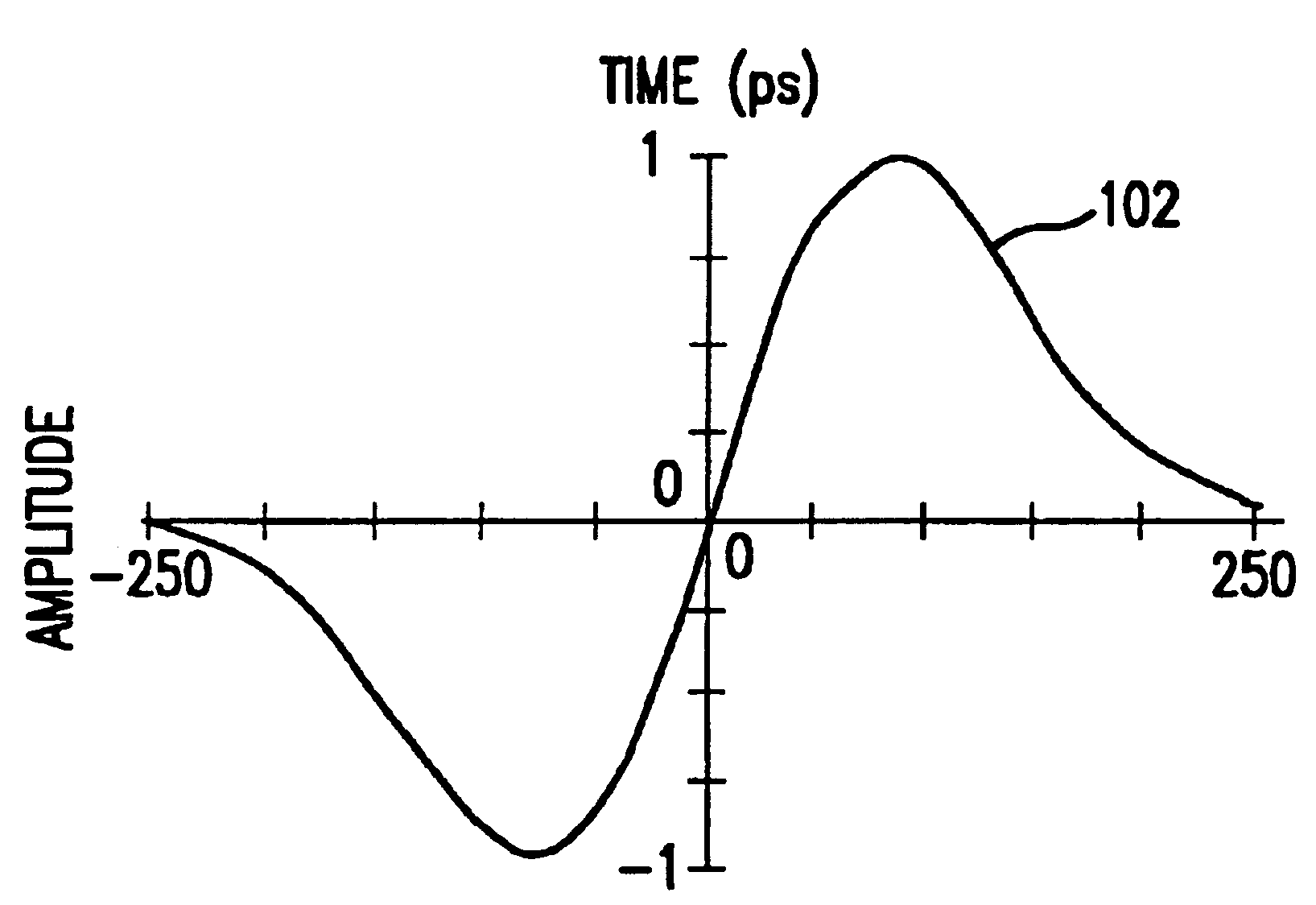
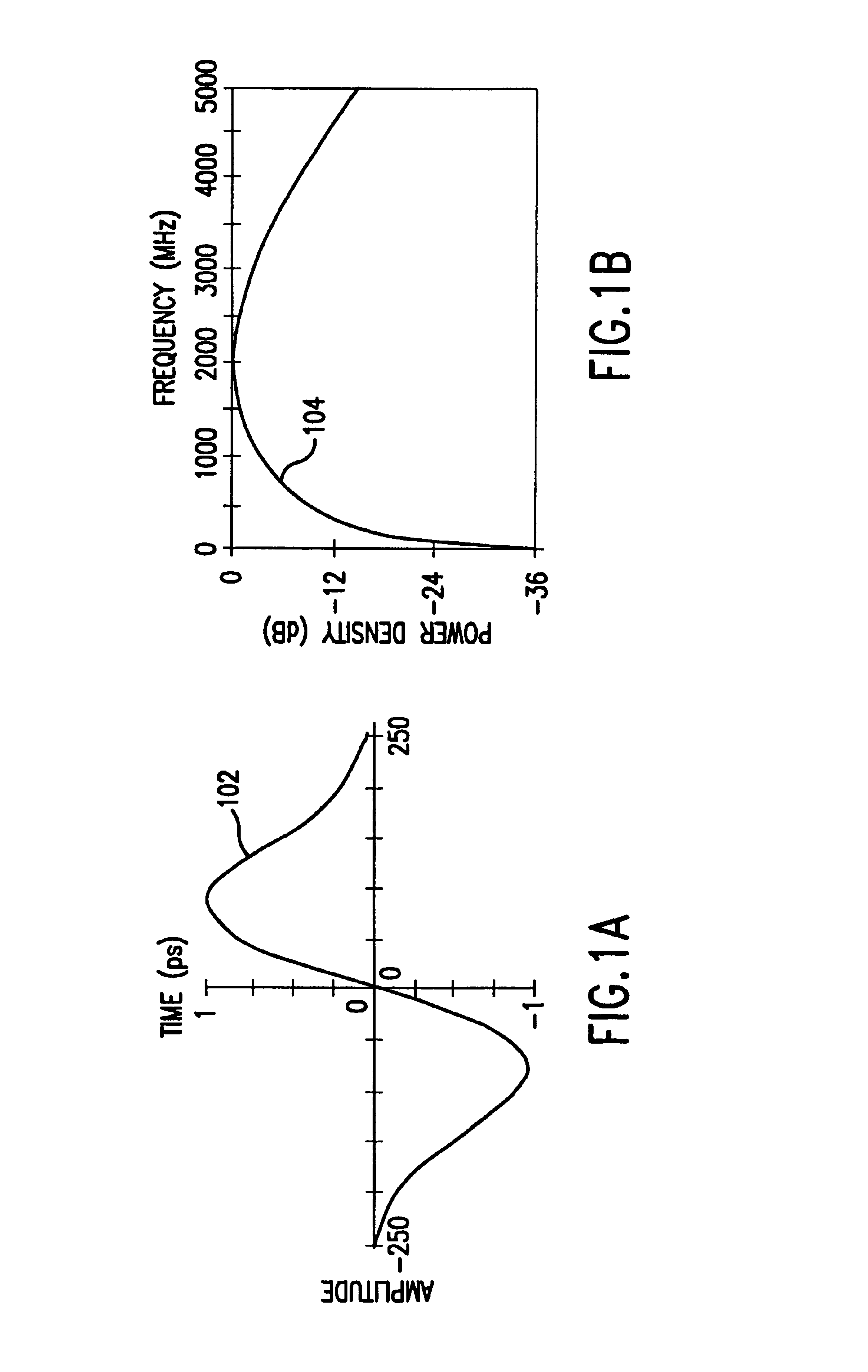
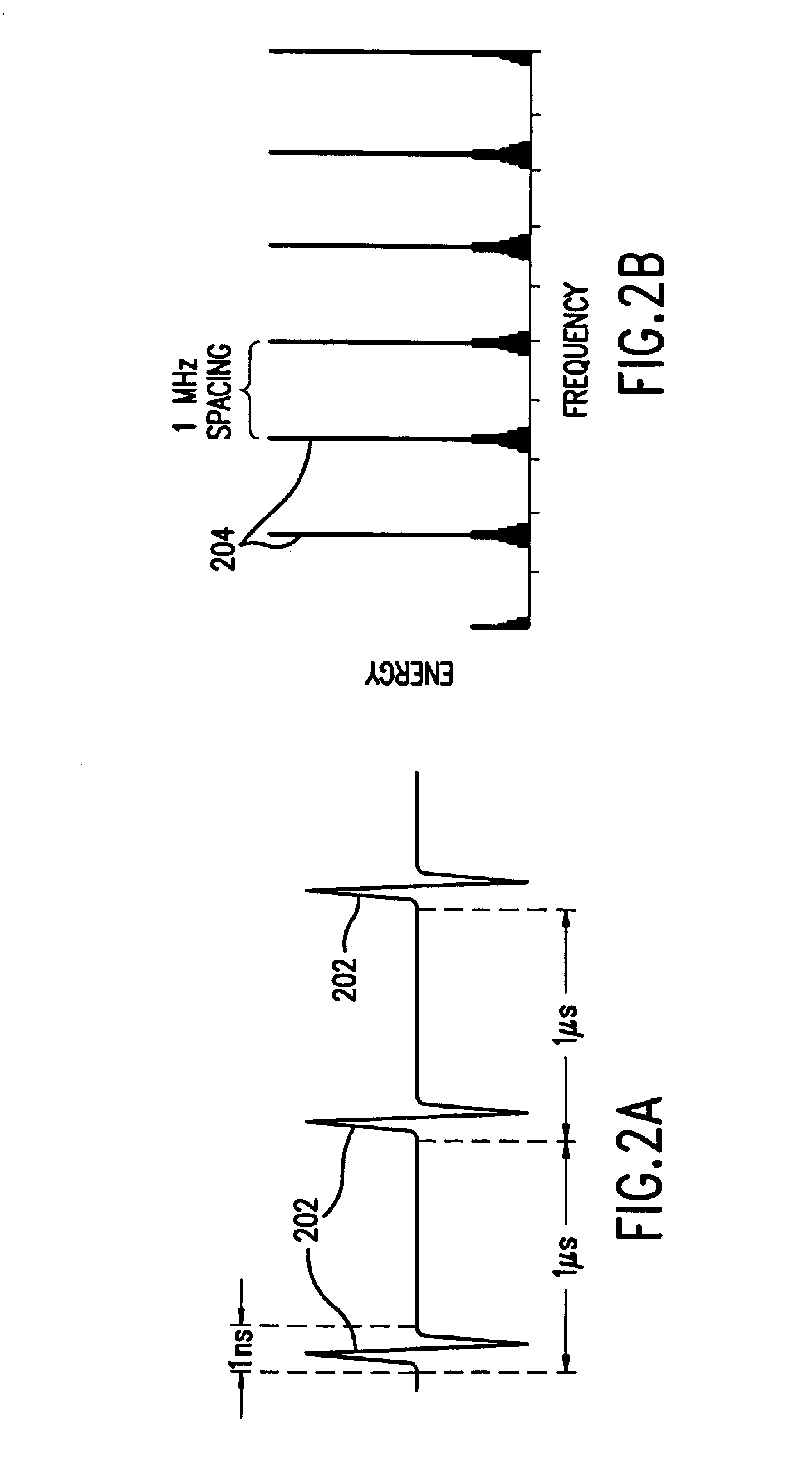
The impulse radio communication system is an ultrawide-band time domain system that operates in the time domain and uses one or more subcarriers to provide channelization, smoothing and fidelity. A single impulse radio transmission (e.g., a link) can therefore communicate many independent channels simultaneously by employing different subcarriers for each channel.

The impulse radio transmitter according to the present invention uses modulated subcarrier(s) for time positioning a periodic timing signal or a coded timing signal. Alternatively, the coded timing signal can be mixed (or summed) with the modulated subcarrier(s) and the resultant signal used to time modulate the periodic timing signal. Direct digital modulation of data is another form of subcarrier modulation for impulse radio signals. Direct digital modulation can be used alone to time modulate the periodic timing signal or the direct digitally modulated periodic timing signal can be further modulated with one o...


PUM


Abstract

An impulse radio communications system using one or more subcarriers to communicate information from an impulse radio transmitter to an impulse radio receiver. The impulse radio communication system is an ultrawide-band time domain system. The use of subcarriers provides impulse radio transmissions added channelization, smoothing and fidelity. Subcarriers of different frequencies or waveforms can be used to add channelization of impulse radio signals. Thus, an impulse radio link can communicate many independent channels simultaneously by employing different subcarriers for each channel. The impulse radio uses modulated subcarrier(s) for time positioning a periodic timing signal or a coded timing signal. Alternatively, the coded timing signal can be summed or mixed with the modulated subcarrier(s) and the resultant signal is used to time modulate the periodic timing signal. Direct digital modulation of data is another form of subcarrier modulation for impulse radio signals. Direct digital modulation can be used alone to time modulate the periodic timing signal or the direct digitally modulated the periodic timing signal can be further modulated with one or more modulated subcarrier signals. Linearization of a time modulator permits the impulse radio transmitter and receiver to generate time delays having the necessary accuracy for impulse radio communications.

Description

BACKGROUND OF THE INVENTION1. Field of the InventionThe present invention relates to the field of communications, and more particularly, the present invention relates to ultrawide-band impulse communication systems and methods employing subcarriers.2. Background ArtDesigners of radio technology for personal communications devices, medical and military devices, and the like, are currently faced with several development challenges. Low power consumption, reuse of available spectrum, channelization and cost are four of the main issues.These issues are addressed in part by an emerging, revolutionary technology called impulse radio communications (hereafter called impulse radio). Impulse radio was first fully described in a series of patents, including U.S. Pat. No. 4,641,317 (issued Feb. 3, 1987), U.S. Pat. No. 4,813,057 (issued Mar. 14, 1989), U.S. Pat. No. 4,979,186 (issued Dec. 18, 1990) and U.S. Pat. No. 5,363,108 (issued Nov. 8, 1994), all to Larry W. Fullerton. These patent docume...

Claims


Application Information

Patent Timeline
IPC IPC(8): H04B1/707H04B1/69H04B14/02H04J13/00H04B1/7075H04B1/708H04B1/7163H04B1/7176H04B1/7183H04L27/26
CPCH04B1/69H04B1/70753H04B1/71632H04B1/71635H04B1/7176H04B1/7183H04B14/026H04L27/2601H04B1/71637H04B1/707H04B1/708H04L27/2602H04B2001/6908H04B2201/70707Y02D30/70
Inventor FULLERTON, LARRY W.COWIE, IVAN A.
Owner TDC ACQUISITION HLDG
Why Eureka
Try Eureka