Switching power supply

a power supply and switch technology, applied in the direction of electric variable regulation, process and machine control, instruments, etc., can solve the problems of high waveform distortion, impede the achievement of compact and flat structure, etc., and achieve the effect of reducing the time from the start of the television set to the power turning on, and reducing the initial charge tim

Inactive Publication Date: 2009-01-29
HITACHI LTD
View PDF3 Cites 61 Cited by
  • Summary
  • Abstract
  • Description
  • Claims
  • Application Information

AI Technical Summary

Benefits of technology

[0017]Since the buck-boost switching power supply uses the H bridge circuits, an efficiency at a voltage of AC 100V can be increased.
[0018]The buck-boost switching power supply can initially charge the smoothing output capacitor while controlling a charge current to the capacitor at a constant level upon turning ON the power. For this reason, there can be no risk of an excess current, and the initial charge time can be shortened. For example, a time from turning ON of the power to the start of the televisio

Problems solved by technology

With respect to the point (2), since the prior art requires a relay, this hinders the achievement of a compact and flat structure.
However, since these relays cannot be surface-mounted on the board nor mounted with their sides laid thereon, the relays have heights o

Method used


Image

  • Switching power supply
  • Switching power supply
  • Switching power supply

Examples


embodiment 1

[0033]A first embodiment of the present invention will be explained by referring to FIGS. 1, 2, 3, 4, and 5.

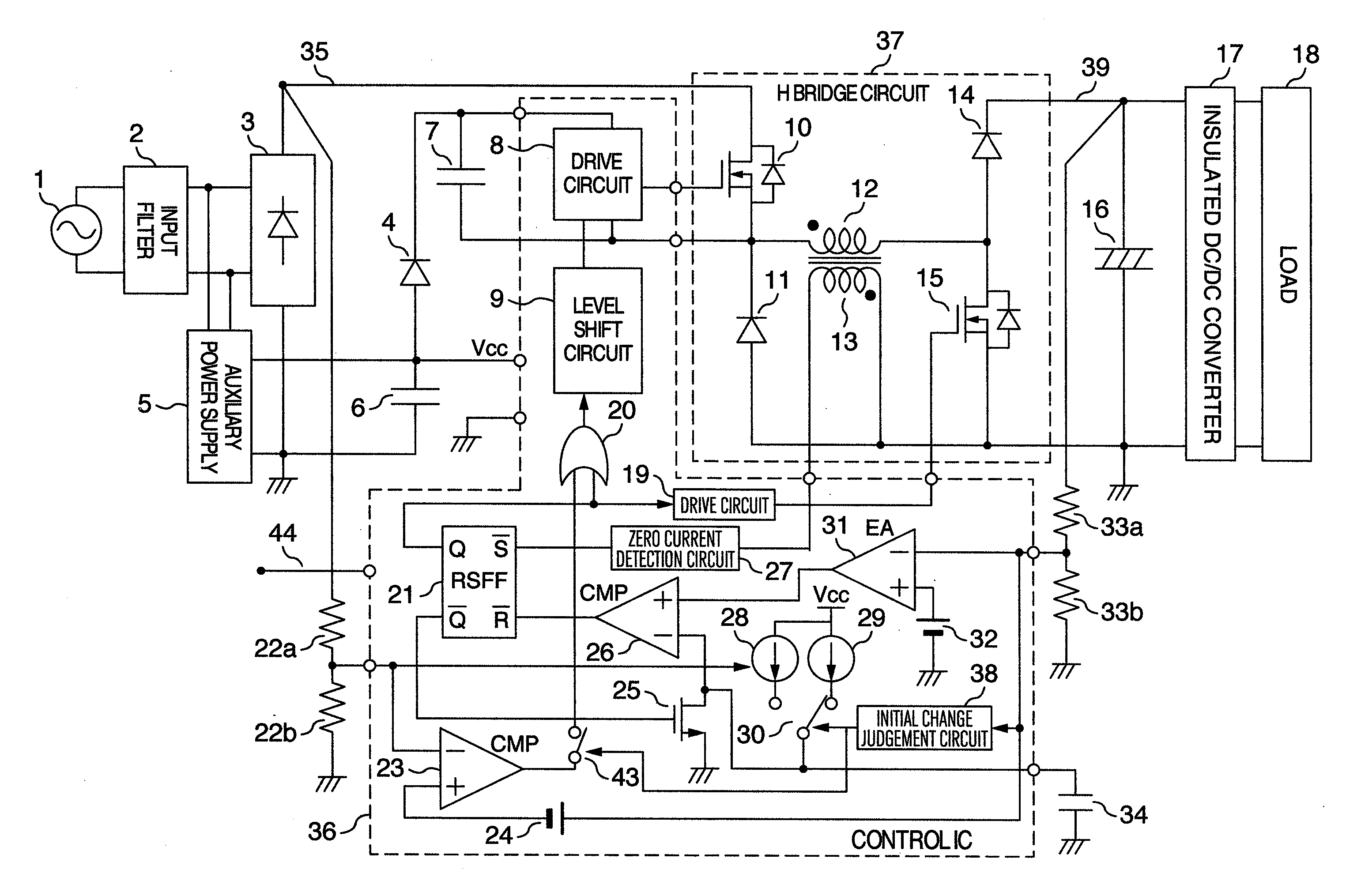
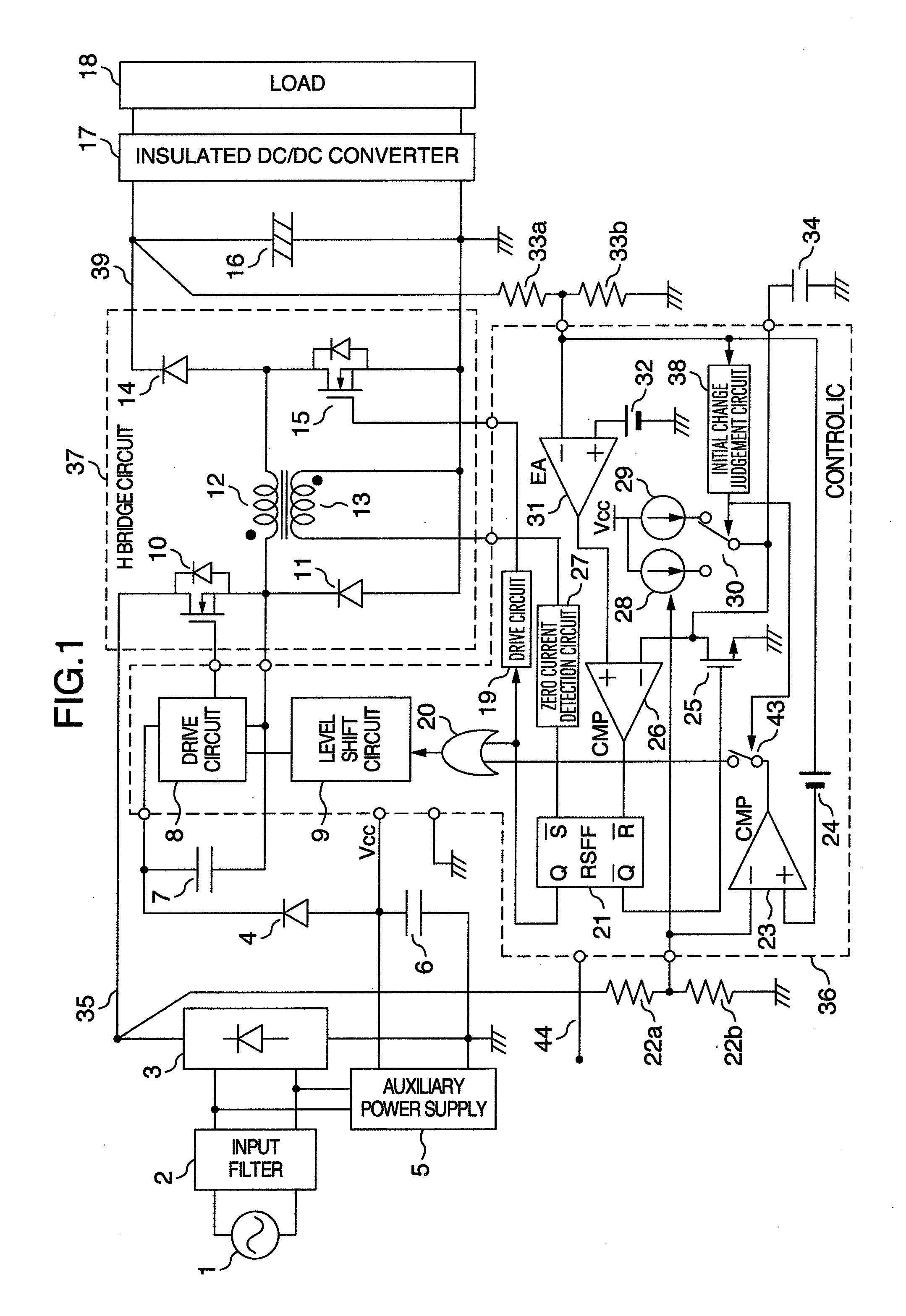
[0034]FIG. 1 is a circuit diagram of a buck-boost switching power supply in accordance with the first embodiment. Explanation will be made as to the arrangement of FIG. 1. A power of an AC power source 1 is passed through an input filter 2 and a rectifier 3 to appear as an input voltage 35 having a full-wave rectified waveform. The input filter 2 is connected with an auxiliary power source 5. A DC output side of the rectifier 3 is connected with a voltage division resistances 22a, 22b and also with a drain of a high side power MOS FET 10. A source of the high side power MOS FET 10 is connected with one end (winding start) of a choke coil 12 and with a cathode of a free wheeling diode 11. An anode of the free wheeling diode 11 is connected to the ground of the rectifier 3. Also connected to the other end of the choke coil 12 are a drain of a low side power MOS FET 15 and an ano...

embodiment 2

[0063]Explanation will then be made as to a second embodiment of the present invention with reference to FIGS. 6, 7, 8, and 9. FIG. 6 shows a main circuit in a buck-boost switching power supply, and FIG. 7 is a control circuit therefor. In FIGS. 6 and 7, constituent elements having the same functions as those in FIG. 1 are denoted by the same reference numerals or symbols. The main circuit of FIG. 6 is different from that in FIG. 1 in that two of the H bridge circuits are prepared as the main circuit and these H bridge circuits are connected in parallel. That is, the interconnection configuration of a high side power MOS FET 10a, a free wheeling diode 11a, a choke coil 12a, a low side power MOS FET 15a, and a boost diode 14a in the H bridge circuit 37 is the same as that of the main circuit in FIG. 1. In addition to this, FIG. 6 includes a high side power MOS FET 10b, a free wheeling diode 11b, a choke coil 12b, a low side power MOS FET 15b, and a boost diode 14b, with the same inte...


PUM


Abstract

A buck-boost converter of an H bridge type having a function for initially charging a smoothing output capacitor without a relay and a rush current preventing resistance. A compact and flat power supply is attained by employing a current critical mode H bridge system for a PFC converter and providing a function of initially charging a smoothing output capacitor to a converter circuit.

Description

BACKGROUND OF THE INVENTION[0001]The present invention relates to a switching power supply which corrects a power factor of an AC input current.[0002]The simplest arrangement of rectifying and smoothing an AC current obtained from an AC power supply to obtain a DC current is to use a diode bridge and a smoothing capacitor. However, this arrangement involves reduction in power factor or increase in input harmonics, because the arrangement becomes a so-called capacitor input type of rectification circuit wherein an input current flows only in the vicinity of the peak of a power voltage. A problem with input harmonics must be treated based on the International Standard, so a measure against the input harmonics is required to be taken according to an input power. To this end, various converters including a PFC (Power Factor Correction) converter and a high power factor converter have been proposes.[0003]A boost type PFC converter in the aforementioned converters has the most general cir...

Claims


Application Information

Patent Timeline
IPC IPC(8): H02M3/335
CPCH02M1/4233Y02B70/126H02M2001/007H02M3/1582Y02B70/10H02M1/007H02M1/0085
Inventor KANOUDA, AKIHIKOKITAMURA, MAKOTOSAKURAMORI, FUSAOMOCHIZUKI, TAKESHI
Owner HITACHI LTD
Why Eureka
Try Eureka